Manuals

2016 kia soul manual

Welcome to the comprehensive owner’s manual for your 2016 Kia Soul! This guide provides essential information regarding operation, maintenance, and safety features.

This manual is designed for all 2016 Kia Soul owners and operators, ensuring a safe and enjoyable driving experience with detailed instructions.

Overview of the Vehicle

The 2016 Kia Soul is a unique and versatile urban compact vehicle, celebrated for its distinctive boxy design and spacious interior. It offers a compelling blend of practicality, style, and affordability, making it a popular choice for diverse drivers. Available in various trims – Base, Plus, Exclaim, and Red Zone – the Soul caters to a wide range of preferences.

This model year features a choice of engines, including a 1.6-liter four-cylinder and a more powerful 2.0-liter option. Key features often include a user-friendly infotainment system, available UVO eServices, and a surprisingly generous cargo capacity for its size. Safety is prioritized with standard features like airbags and available advanced driver-assistance systems. The 2016 Soul aims to deliver a fun and functional driving experience, standing out in the competitive compact car segment.

Target Audience for this Manual

This owner’s manual is specifically crafted for all individuals who own, operate, or maintain a 2016 Kia Soul. It’s intended for both first-time Kia owners and those familiar with the brand, providing comprehensive guidance on vehicle features and operation. Whether you’re a daily commuter, a family seeking a practical vehicle, or an individual appreciating unique style, this manual will prove invaluable.

We’ve designed it to be accessible to drivers of all experience levels, using clear language and detailed illustrations. Technicians performing maintenance or repairs on the vehicle will also find crucial information within these pages. Ultimately, this manual aims to empower every user to maximize the enjoyment and longevity of their 2016 Kia Soul, ensuring safe and informed operation.

Understanding Your 2016 Kia Soul

Dive into the specifics of your vehicle! This section details the VIN location, key features, specifications, and a comprehensive explanation of dashboard symbols.

Vehicle Identification Number (VIN) Location

Locating your 2016 Kia Soul’s Vehicle Identification Number (VIN) is crucial for various reasons, including warranty claims, theft recovery, and vehicle history reports. The VIN is a unique 17-character code specific to your vehicle.

You can find the VIN in several places on your Soul. Firstly, it’s located on the driver’s side dashboard, visible through the windshield. Look for a small metal plate. Secondly, the VIN is printed on the driver’s side doorjamb sticker. Additionally, it’s present on your vehicle registration and insurance documents.

Confirming the VIN’s accuracy is essential. Ensure the number matches across all locations and documents. This unique identifier is vital for any service or official inquiries regarding your 2016 Kia Soul.

Key Features and Specifications

The 2016 Kia Soul boasts a unique and versatile design, offering a blend of practicality and style. Key features include available UVO infotainment system with touchscreen display, Bluetooth connectivity, and a rearview camera. Safety is prioritized with features like Electronic Stability Control (ESC) and an available rearview camera.

Specifications vary by trim level, but generally, the 2016 Soul is powered by a 1.6L or 2.0L four-cylinder engine. Transmission options include a six-speed manual or automatic. Fuel economy ranges from approximately 25-31 MPG combined. Interior space is surprisingly generous for its class, offering ample headroom and cargo capacity.

Available trims include Base, Plus, Exclaim (!), and Red Zone. Each trim adds progressively more features and styling enhancements, catering to diverse driver preferences. The Soul is known for its value and distinctive character.

Dashboard Symbols and Indicators

Understanding the symbols on your 2016 Kia Soul’s dashboard is crucial for safe operation. Warning lights indicate potential issues requiring immediate attention, such as low oil pressure, engine temperature, or brake system malfunctions. These are typically red or amber in color.

Indicator lights, often green or blue, communicate the status of various systems like headlights, turn signals, and cruise control. Familiarize yourself with the meaning of each symbol to promptly address any concerns. A comprehensive list is provided in this manual with detailed explanations.

Pay close attention to the airbag indicator, ABS warning light, and the check engine light. Ignoring these signals could lead to more significant problems. Regularly check your dashboard for any illuminated symbols and consult this manual for guidance.

Operating Your 2016 Kia Soul

This section details the proper procedures for operating your 2016 Kia Soul, covering everything from starting the engine to utilizing driving modes and essential checks.

Starting and Stopping the Engine

Starting the Engine: Ensure the parking brake is engaged and the gear selector is in ‘P’ (Park) or ‘N’ (Neutral). Insert the key into the ignition or, if equipped, press the start/stop button while firmly pressing the brake pedal. The engine will start. Allow a brief moment for oil circulation, especially in cold weather.

Stopping the Engine: Gently apply the brakes to bring the vehicle to a complete stop. Shift the gear selector to ‘P’ (Park). Engage the parking brake. Press the start/stop button (if equipped) or turn the ignition key to the ‘LOCK’ position. Remove the key. Never turn off the engine while driving.

Emergency Stop: In an emergency, safely steer the vehicle to a stop and immediately engage the parking brake. Turn off the engine and, if possible, activate hazard lights.

Driving Modes and Controls

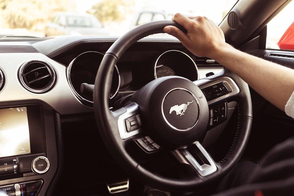
Steering Wheel Controls: The steering wheel integrates controls for audio, cruise control, and Bluetooth connectivity. Familiarize yourself with their location and function for safe operation while driving. Adjust steering wheel tilt and telescopic columns for optimal comfort.

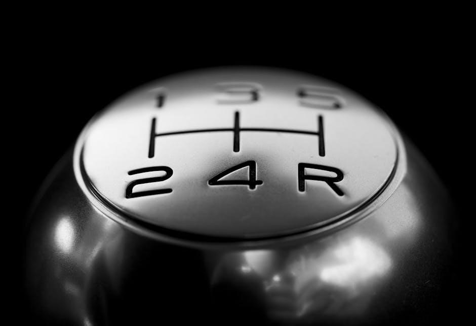
Gear Selector: The gear selector offers positions for Park (P), Reverse (R), Neutral (N), and Drive (D). Some models include a Sport mode for enhanced performance. Always ensure the vehicle is fully stopped before shifting gears.

Pedals: The accelerator pedal controls speed, while the brake pedal slows or stops the vehicle. Use smooth, controlled pedal inputs for a comfortable driving experience. Be mindful of pedal sensitivity.

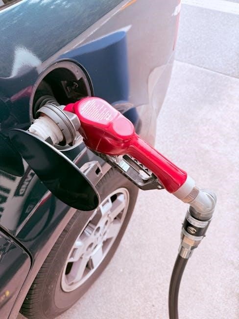
Fueling and Fluid Checks

Fueling: Your 2016 Kia Soul requires unleaded gasoline with an octane rating of 87 or higher. Locate the fuel door release, fill the tank, and replace the cap securely. Avoid overfilling. Always fuel in a well-ventilated area and never smoke near the fuel tank.

Engine Oil: Regularly check the engine oil level using the dipstick. Ensure the level is between the minimum and maximum marks. Top up with the recommended oil type if necessary. Low oil levels can cause engine damage.

Coolant & Other Fluids: Inspect coolant, brake fluid, power steering fluid, and windshield washer fluid levels periodically. Add fluids as needed, using the correct type specified in this manual.

Maintenance and Care

Maintaining your 2016 Kia Soul is crucial for longevity and performance. Follow the recommended schedule for optimal vehicle health and reliability, ensuring safety.

Recommended Maintenance Schedule

To ensure the longevity and optimal performance of your 2016 Kia Soul, adhering to a strict maintenance schedule is paramount. Every 7,500 miles or six months, whichever comes first, requires an oil and filter change, tire rotation, and a comprehensive multi-point inspection.

At 15,000 miles, supplement this with a cabin air filter replacement and a thorough inspection of the brake system, including pads, rotors, and lines. Further, at 30,000 miles, the engine air filter should be replaced, along with a coolant flush.

Don’t neglect the transmission fluid; it should be inspected and potentially replaced around 60,000 miles. Regularly checking and topping off all fluid levels – brake, power steering, windshield washer – is also vital. Following this schedule will help prevent costly repairs and maintain your Soul’s value.

Tire Information and Maintenance

Maintaining proper tire pressure is crucial for safety, fuel efficiency, and tire lifespan on your 2016 Kia Soul. Refer to the sticker located on the driver’s side doorjamb for the recommended PSI (pounds per square inch). Check tire pressure monthly, and always when the temperature changes significantly.

Regular tire rotations – every 7,500 miles – promote even wear and extend tire life. Inspect tires for uneven wear patterns, cuts, bulges, or embedded objects. The minimum tread depth for safe operation is 2/32 of an inch; use a tread depth gauge to verify.

Ensure tires are properly aligned to prevent premature wear. When replacing tires, use the same size and type as originally equipped by Kia. Ignoring tire maintenance can compromise handling and braking performance.

Fluid Levels and Replacement

Regularly checking and maintaining proper fluid levels is vital for your 2016 Kia Soul’s performance and longevity. Key fluids include engine oil, coolant, brake fluid, power steering fluid, and windshield washer fluid.

Check engine oil levels at least once a month using the dipstick, adding oil as needed to maintain the ‘full’ mark. Coolant levels should be inspected in the reservoir when the engine is cold. Brake fluid and power steering fluid levels are also checked via their respective reservoirs.

Follow the recommended maintenance schedule for fluid replacement intervals. Using the correct type of fluid, as specified in this manual, is essential. Improper fluids can cause damage to vehicle components. Dispose of used fluids responsibly at a designated recycling center.

Safety Features

Your 2016 Kia Soul is equipped with advanced safety systems, including an airbag system, anti-lock braking (ABS), and electronic stability control (ESC) for protection.

Airbag System

The 2016 Kia Soul’s airbag system is a crucial component of its safety features, designed to provide occupant protection during a collision. This system includes front airbags for both driver and passenger, as well as seat-mounted side airbags and curtain airbags.

Airbags are designed to work with seatbelts, not replace them. Always ensure all occupants are properly restrained. The airbags deploy rapidly and with significant force, so maintaining a safe distance is vital.

Important Considerations: Never place rear-facing child seats in the front passenger seat if the airbag cannot be deactivated. Regularly inspect the airbag warning light on the dashboard; if it illuminates and remains on, have the system inspected by a qualified technician immediately. Improper repairs can compromise the system’s effectiveness.

Understanding the airbag system’s operation and limitations is essential for maximizing safety.

Anti-lock Braking System (ABS)

Your 2016 Kia Soul is equipped with an Anti-lock Braking System (ABS), designed to help maintain steering control during hard braking situations and reduce stopping distances. ABS prevents wheel lockup, allowing you to steer around obstacles while braking.

When ABS activates, you may feel a pulsating sensation in the brake pedal and hear a clicking noise – this is normal and indicates the system is functioning correctly. Maintain firm and continuous pressure on the brake pedal during ABS activation; do not pump the brakes.

The ABS warning light on the dashboard will illuminate if a system malfunction is detected. If this occurs, have the system inspected and repaired by a qualified technician. Regular brake inspections are crucial for optimal ABS performance and overall safety.

Electronic Stability Control (ESC)

The 2016 Kia Soul features Electronic Stability Control (ESC), a vital safety system designed to help prevent skidding and maintain directional control, especially during emergency maneuvers or on slippery surfaces. ESC monitors steering direction and vehicle motion, automatically applying brakes to individual wheels as needed.

When ESC activates, you may notice a slight braking sensation and the ESC indicator light flashing on the dashboard. Continue steering in the intended direction; do not overcorrect. ESC works in conjunction with the ABS to provide enhanced stability.

The ESC system can be temporarily disabled (consult your owner’s manual for specific instructions), but it’s generally recommended to keep it activated for optimal safety. A steady ESC light indicates a system malfunction – seek professional service immediately.
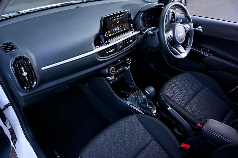
Interior Features

Discover the comfortable and technologically advanced interior of your 2016 Kia Soul! Explore features like the audio system, climate controls, and optional navigation system.

Audio System and Controls

Your 2016 Kia Soul’s audio system is designed for an immersive listening experience. The system typically features an AM/FM radio, a CD player, and auxiliary/USB inputs for connecting external devices. Many models include Bluetooth connectivity for wireless audio streaming and hands-free calling.

Operating the System: The primary controls are located on the center stack. Use the power button to turn the system on/off. The volume knob adjusts the sound level, while the tuning knob selects radio stations. Buttons are provided for source selection (Radio, CD, AUX, USB, Bluetooth). Steering wheel-mounted controls allow for convenient operation while driving.

Bluetooth Pairing: To pair a device, access the Bluetooth menu on the audio system and follow the on-screen prompts. Ensure your device is in pairing mode. Once paired, you can stream audio and make calls. Refer to the full owner’s manual for detailed instructions and troubleshooting tips.

Navigation System (if equipped)

If your 2016 Kia Soul is equipped with a navigation system, it provides turn-by-turn directions and points of interest. The system is typically controlled via a touchscreen display. Before starting a journey, ensure the map data is up-to-date for the most accurate routing.

Entering a Destination: You can enter a destination by address, point of interest, or coordinates. The system will calculate the optimal route based on your preferences (fastest, shortest, etc.). Voice guidance provides audible directions during your drive.

Map Features: The navigation system offers features like traffic updates (depending on subscription status), lane guidance, and speed limit displays. Explore the menu options to customize the map view and settings. Refer to the separate navigation system manual for detailed instructions on all features and troubleshooting.

Climate Control System

Your 2016 Kia Soul’s climate control system allows you to adjust the temperature and airflow within the vehicle. Manual systems feature dials for temperature, fan speed, and vent selection. Automatic systems maintain a set temperature automatically.

Operation: To use the system, simply adjust the controls to your desired settings. The recirculation button allows you to circulate interior air, useful for quickly cooling or heating the cabin. The A/C button activates the air conditioning for cooling.

Ventilation: Select from various vent modes – face, feet, defrost, or a combination – to direct airflow. Ensure proper ventilation to prevent window fogging. Regularly check and replace the cabin air filter for optimal air quality and system performance.

Troubleshooting Common Issues

This section offers guidance for resolving frequently encountered problems with your 2016 Kia Soul, covering engine, electrical, and transmission concerns.

Engine Problems

Difficulty Starting: If your 2016 Kia Soul fails to start, first check the battery connections and ensure sufficient fuel. A faulty starter motor or a problem with the ignition system could also be the cause. Listen for clicking sounds when attempting to start.

Rough Idling: A rough idle may indicate issues with the spark plugs, fuel injectors, or vacuum leaks. Inspect these components and consider a professional diagnostic check. Dirty air filters can also contribute to this issue.

Overheating: Overheating is a serious concern. Check the coolant level and look for leaks in the cooling system. A malfunctioning thermostat or water pump could also be responsible. Never open the radiator cap when the engine is hot.

Unusual Noises: Knocking or ticking sounds from the engine require immediate attention. These could indicate internal engine damage and necessitate professional repair. Ignoring these sounds can lead to more significant problems.

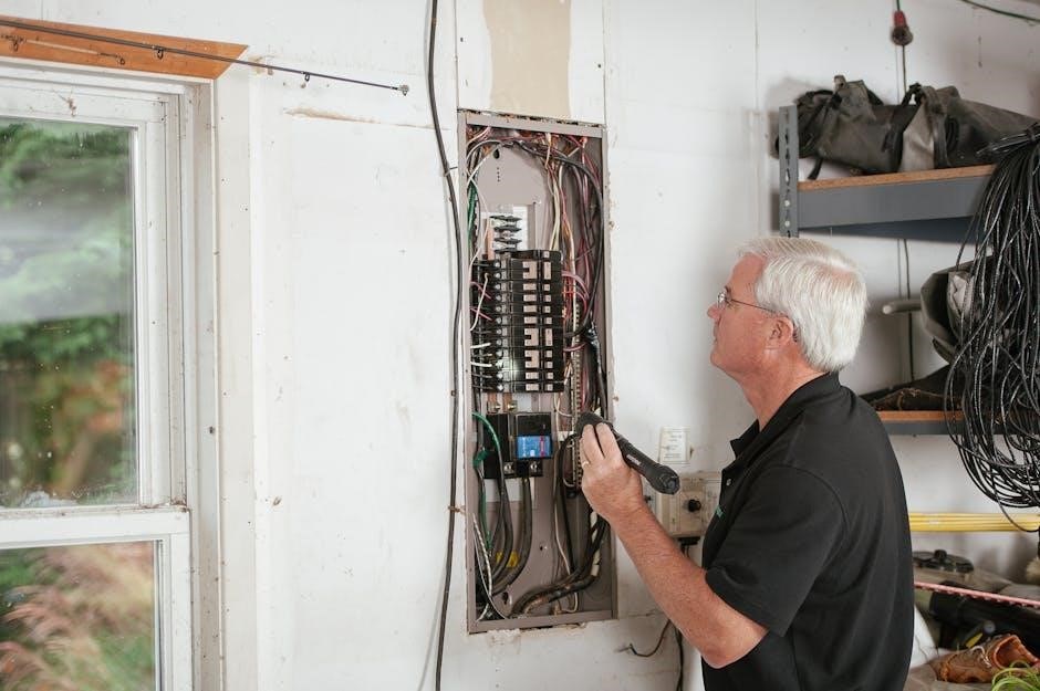
Electrical System Issues

Battery Drain: A consistently draining battery could stem from a faulty charging system, a parasitic draw, or leaving lights on. Have the alternator and battery tested. Identify and address any accessories drawing power when the vehicle is off.

Faulty Lights: Check bulbs and fuses if lights aren’t functioning. Repeated bulb failures might indicate a wiring issue or a problem with the light assembly itself. Ensure proper grounding for all lighting components.

Power Window/Lock Problems: Issues with power windows or locks often relate to faulty switches, motors, or wiring. Inspect the fuse box first, then consider professional diagnosis and repair.

Warning Light Illumination: A lit “Check Engine” or battery warning light requires investigation. Utilize an OBD-II scanner to retrieve diagnostic trouble codes (DTCs) for pinpointing the source of the problem.

Transmission Concerns

Shifting Issues: Difficulty shifting gears, harsh or delayed engagement, or slipping gears are key indicators of transmission problems. Check the transmission fluid level and condition – low or dark fluid can cause issues;

Unusual Noises: Whining, clunking, or humming sounds emanating from the transmission during operation warrant immediate attention. These noises often signal internal damage or wear.

Fluid Leaks: Inspect the area around the transmission for any signs of fluid leaks. Reddish-brown fluid indicates a transmission fluid leak, requiring prompt repair to prevent further damage.

Warning Lights: A flashing or solid transmission warning light on the dashboard signifies a serious issue. Have the vehicle diagnosed by a qualified mechanic to determine the cause and necessary repairs.

little giant pump manual

Little Giant Pump Manual: A Comprehensive Guide

This manual details troubleshooting, maintenance, and repair for Little Giant pumps, including sump, pool cover, and condensate models.
It covers topics like GFCI resets, oil changes with AW32 hydraulic oil, and component replacements like the CV-10 check valve.

Understanding Little Giant Pumps

Little Giant pumps are renowned for their durability and reliability across various applications, from basement sump pits to pool covers and HVAC condensate removal. These pumps utilize different switching mechanisms, notably internal and tethered float switches, as seen in the 6-CIA model, to automatically activate and deactivate pumping cycles based on water levels.

Proper operation relies on understanding the pump’s specific design and intended use. Regular inspection is crucial, alongside awareness of potential issues like GFCI tripping, indicating electrical concerns. Furthermore, recognizing warranty limitations, such as those concerning brush wear in specific models (like the 35-OM) or impeller/cam issues in others (PP-1, PP-12, PP-230), is vital for informed ownership.

Pump Types and Applications

Little Giant offers diverse pumps for specific needs: sump pumps (like the 6-CIA), pool cover pumps, and condensate pumps (VCC, VCMA, VCL series) each serve unique purposes.

Sump Pump Models (e.g., 6-CIA)

Little Giant sump pumps, such as the popular 6-CIA model, are designed to effectively remove water from basements and crawl spaces. These pumps utilize either an internal or tethered float switch to automatically activate when water levels rise, preventing flooding.

If a sump pump fails to operate, a common issue is being undersized for the incoming water volume. Proper sizing is crucial for reliable performance. Troubleshooting includes verifying the pump isn’t straining to keep up with inflow.

Regular inspection of the intake and impeller is vital; clogs can significantly reduce pumping capacity. Remember to always allow the pump to cool before any servicing or inspection procedures are undertaken for safety.

Pool Cover Pump Models

Little Giant pool cover pumps are specifically engineered to efficiently remove accumulated rainwater and debris from swimming pool covers. These pumps prevent excessive water weight, which can damage the cover and potentially the pool structure itself.

A frequently encountered issue with these pumps is erratic behavior, often stemming from a blockage. A simple yet effective solution, as demonstrated by user experiences, involves cleaning the small hole located above the hose outlet.

This clears any obstructions hindering proper water flow and restores the pump to optimal functionality. Regular cleaning and inspection of this outlet hole are recommended preventative maintenance steps to ensure consistent performance.

Condensate Pump Models (VCC, VCMA, VCL)

Little Giant condensate pumps, including the VCC, VCMA, and VCL series, are designed to remove water generated by air conditioning, refrigeration, and dehumidification systems. These pumps prevent water damage and ensure efficient operation of HVAC equipment.

The CV-10 check valve is a crucial component for these models, preventing backflow and maintaining prime. Replacement is straightforward, with the CV-10 readily available (approximately $10.95 as of a recent report).

Proper installation and maintenance, including regular inspection of the check valve and ensuring clear drainage lines, are vital for reliable performance. These pumps are covered under warranty, excluding brush wear and impeller/cam issues.

Troubleshooting Common Issues

Diagnosing problems involves checking for electrical faults (GFCI tripping), ensuring proper pump sizing, and clearing obstructions in the intake or impeller.

Pump Not Starting

If the Little Giant pump fails to start, initial troubleshooting should focus on the electrical supply. First, verify that the pump is receiving power and check if the Ground Fault Circuit Interrupter (GFCI) has been activated. Resetting the GFCI is a crucial first step.

Next, meticulously inspect all electrical connections for looseness, corrosion, or damage. Ensure proper wiring and secure connections. If the pump still doesn’t start, consider whether the float switch is functioning correctly, as it controls pump activation. Remember to always allow the pump to cool before any servicing or inspection of electrical components to prevent potential hazards.

GFCI Tripping and Resetting

A frequently encountered issue is a tripping GFCI (Ground Fault Circuit Interrupter). This safety device protects against electrical shock, and tripping indicates a potential ground fault. Before assuming a pump failure, always attempt a GFCI reset. Locate the GFCI outlet serving the pump and press the “Reset” button.

If the GFCI immediately trips again, do not continue attempting resets. This signals a persistent electrical issue requiring investigation. Inspect the pump’s power cord for damage and check for moisture near the electrical connections. A recurring trip suggests a fault within the pump itself, necessitating professional evaluation or repair. Prioritize safety and avoid repeated resets.

Electrical Connection Inspection

Thoroughly inspect all electrical connections associated with the Little Giant pump. Begin by ensuring the pump is disconnected from power before any inspection. Examine the power cord for cuts, abrasions, or exposed wiring. Check the connections at the GFCI outlet, ensuring they are secure and free from corrosion.

Verify the wiring within the pump’s housing (if accessible and you are qualified to do so) is intact and properly connected. Look for loose wires or signs of overheating. If any damage is found, do not attempt a repair yourself; consult a qualified electrician. Proper electrical connections are crucial for safe and reliable pump operation.

Pump Running But Not Pumping

If the Little Giant pump is running but failing to move water, several issues could be present. A common cause is an undersized pump – if more water enters than the pump can handle, it will run continuously without effectively removing the liquid.

Another frequent problem is a clogged intake or impeller. Debris can obstruct the pump’s inlet, preventing water from being drawn in. Similarly, obstructions within the impeller housing can hinder its rotation and pumping action. Inspect and clear any blockages. Ensure the pump’s capacity matches the water volume requirements to avoid this frustrating situation.

Undersized Pump for Water Volume

An undersized Little Giant pump struggles to keep up with incoming water, leading to continuous operation without noticeable water removal. This occurs when the pump’s capacity (gallons per hour) is insufficient for the volume of water needing to be pumped.

JustAnswer Plumbing experts confirm this is a primary cause of pump failure to effectively drain. Carefully assess the water inflow rate and select a pump with a higher capacity if necessary. Consider factors like rainfall intensity, drainage area size, and potential for groundwater seepage when determining the appropriate pump size for your application.

Clogged Intake or Impeller

A common reason for a Little Giant pump running but not pumping is a blockage in the intake or around the impeller. Debris like leaves, dirt, or small objects can obstruct water flow, hindering the pump’s ability to function correctly.

Trouble Free Pool forums highlight a specific issue: a clogged hole above the hose outlet. Regularly inspect and clear the intake screen and impeller area. Disconnect the power before any inspection! Carefully remove any obstructions to restore proper water flow and pump performance. A clean impeller ensures efficient operation and prevents motor strain.

Erratic Pump Behavior

If your Little Giant pump exhibits inconsistent or unpredictable operation, several factors could be at play. This can manifest as intermittent pumping, reduced flow, or unusual noises. A key area to investigate, as noted in online forums, is the small hole located above the hose outlet.

This hole can become clogged, disrupting the pump’s vacuum and causing erratic behavior. Cleaning this opening often resolves the issue. Additionally, ensure the float switch is functioning correctly and isn’t obstructed. Inspect for any loose connections or damaged wiring that might contribute to inconsistent performance.

Cleaning the Hose Outlet Hole

A frequently reported solution for erratic Little Giant pump behavior involves cleaning the small hole situated directly above the hose outlet. This seemingly minor detail is crucial for proper pump function, as it maintains the necessary vacuum for efficient water removal.

Debris can easily accumulate in this opening, hindering airflow and causing inconsistent pumping. To clean it, disconnect the pump from power and carefully remove any obstructions using a small tool – avoid damaging the surrounding plastic. Trouble Free Pool forums highlight this as a common fix, often restoring the pump to full operational capacity after cleaning.

Maintenance and Repair

Regular inspections, oil changes using AW32 hydraulic oil, and gasket replacements are vital for extending the lifespan of your Little Giant pump.

Regular Inspection Procedures

Consistent inspection is key to preventative maintenance and avoiding costly repairs. Begin by visually checking the pump’s exterior for any cracks or damage. Ensure all electrical connections are secure and free from corrosion; promptly address any issues.

Inspect the pump’s intake and discharge for obstructions. Regularly examine the float switch, verifying its free movement and proper operation – whether internal or tethered. Listen for unusual noises during operation, which could indicate impeller issues or bearing wear.

Don’t forget to check the hose outlet hole for any buildup, as this can cause erratic behavior. Document these inspections to track pump performance over time and identify potential problems early on, maximizing its operational life.

Oil Change (AW32 Hydraulic Oil)

Maintaining proper lubrication is crucial for Little Giant pump longevity. Use only AW32 hydraulic oil for optimal performance; a 4-litre jug typically costs around $47.00. Before beginning, disconnect the pump from the power source. Locate the oil drain plug and carefully remove it, allowing the old oil to drain completely into a suitable container.

Once drained, replace the plug with a new gasket, applying gasket sealer for a watertight seal. Then, add fresh AW32 hydraulic oil through the fill port until the appropriate level is reached – consult your specific model’s documentation for capacity.

Dispose of the used oil responsibly, following local environmental regulations. Regular oil changes, typically annually, ensure smooth operation and prevent premature wear.

Gasket Replacement

Replacing gaskets is essential during pump repair to maintain a watertight seal and prevent leaks. When disassembling the pump for maintenance, carefully inspect all gaskets for signs of wear, cracking, or deterioration. Before installing a new gasket, ensure all mating surfaces are clean and free of debris.

Apply a thin, even coat of gasket sealer to both sides of the new gasket. This enhances the seal and prevents future leaks. Align the gasket correctly and securely fasten the components together, tightening bolts to the manufacturer’s specified torque.

A new gasket, alongside AW32 hydraulic oil, can significantly extend the life of your Little Giant pump, costing around $10.00 ― $10.95.

Component Replacement

Replacing worn components, such as check valves (CV-10) and float switches, restores pump functionality. Proper replacement ensures optimal performance and extends the pump’s lifespan.

Check Valve Replacement (CV-10)

The Little Giant CV-10 check valve is crucial for preventing backflow in condensate pumps (VCC, VCMA, VCL-14, and VCL-24). When replacing, ensure the 1/4-inch MNPT x 3/8-inch barbed connections are secure. Begin by disconnecting power to the pump. Carefully remove the old CV-10, noting its orientation.

Apply a suitable gasket sealer to the threads of the new CV-10 before installation. Hand-tighten initially, then use a wrench for a snug fit – avoid over-tightening, which can damage the valve or pump housing. A new CV-10 typically costs around $10.95. Proper installation prevents water from draining back into the collection tank when the pump shuts off, maintaining prime and efficient operation.

Float Switch Functionality (Internal/Tethered)

Little Giant pumps, like the 6-CIA sump pump model, utilize either an internal or tethered float switch to automatically activate pumping operations. The float switch rises with the water level, triggering the pump when it reaches a predetermined height.

Internal float switches are contained within the pump housing, while tethered floats move more freely on an arm. Regularly inspect the float’s range of motion, ensuring it isn’t obstructed by debris. A malfunctioning float switch is a common cause of pump failure. If the pump doesn’t activate or cycles erratically, check the float for damage or binding before considering other repairs.

Warranty Information

Little Giant offers warranty coverage on its pumps (PP-230, Cooler King) from the user’s purchase date. However, brush wear and impeller/cam issues are excluded.

Warranty Coverage Details

Little Giant warranties cover defects in materials and workmanship under normal use. This coverage extends to pumps like the PP-230 and Cooler King models, beginning from the original date of purchase by the end-user. The warranty ensures the product will be free from defects for a specified period, allowing for repair or replacement at Little Giant’s discretion.

However, it’s crucial to understand that certain components and conditions are specifically excluded from this warranty. These exclusions are in place due to the nature of wear and tear experienced during pump operation. Proper maintenance, as outlined in this manual, is essential to maintain warranty validity. Any alterations or misuse of the pump may also void the warranty.

Limitations of Warranty (Brush Wear, Impeller/Cam)

Specifically, Little Giant’s warranty does not cover wear on brushes within Model 35-OM. This is due to the inherent nature of brush-type motors and their expected lifespan with regular use. Similarly, the warranty excludes damage or failure of the impeller or cam in Models PP-1, PP-12, and PP-230.

These components are considered wear items and are subject to degradation over time. If a product fails due to brush wear or impeller/cam issues within the warranty period, Little Giant reserves the right to repair or replace the unit at their option, but may charge for the replacement of these specific parts. This ensures fair coverage while acknowledging typical operational wear.

Safety Precautions

Always allow the pump to cool completely before any servicing; Exercise extreme caution when working with electrical components to prevent shock or damage.

Allowing Pump to Cool Before Servicing

Prior to undertaking any inspection, maintenance, or repair procedures on your Little Giant pump, it is absolutely crucial to ensure the unit has been allowed to cool down completely. Operating on a hot pump presents a significant risk of burns from heated components and potentially damaging sensitive parts.

The pump motor generates substantial heat during operation. Disconnecting power is the first step, but residual heat remains. Allow ample time for the pump housing, motor, and any fluids within to dissipate heat before touching any part. This cooling period minimizes the risk of injury and ensures a safer working environment. Ignoring this precaution could lead to personal harm and compromise the pump’s functionality.

Always prioritize safety and allow sufficient cooling time before beginning any service work.

Working with Electrical Components

Extreme caution is paramount when working with the electrical components of your Little Giant pump. Electricity poses a serious safety hazard, and improper handling can result in severe injury or even fatality. Always disconnect the pump from its power source – unplug it or switch off the circuit breaker – before commencing any electrical work.

If a GFCI (Ground Fault Circuit Interrupter) device has been activated, thoroughly inspect all electrical connections for damage or corrosion. Resetting the GFCI should only occur after verifying the safety of the wiring and connections. Never attempt to bypass or disable a GFCI device.

If you are uncomfortable or lack experience working with electrical systems, consult a qualified electrician.

Little Giant Pump Parts

Locating the correct replacement parts is crucial for maintaining your Little Giant pump. Understanding part numbers, like the CV-10 check valve, ensures compatibility and proper function.

Locating Replacement Parts

Finding the right replacement parts for your Little Giant pump is essential for effective repairs and continued operation. Several avenues exist for sourcing these components. Online retailers specializing in plumbing and pump supplies often carry a comprehensive inventory of Little Giant parts. Local plumbing supply stores are also valuable resources, allowing for in-person consultation and immediate availability of common parts like check valves (CV-10) and gaskets.

When ordering, having the pump’s model number readily available is critical. This ensures you receive parts specifically designed for your unit. Detailed parts diagrams are often available online through the Little Giant website or distributor sites, aiding in accurate identification. Don’t hesitate to contact Little Giant’s customer support for assistance if you’re unsure about the correct part number or compatibility.

Understanding Part Numbers

Little Giant part numbers are crucial for accurate ordering and ensuring compatibility with your specific pump model. These numbers are typically found on the pump’s nameplate, in the parts list of the owner’s manual, or on the original packaging. The part number provides a unique identifier for each component, preventing confusion and ensuring the correct replacement is received.

Part numbers often consist of letters and numbers, sometimes including dashes or prefixes. These segments can indicate the part’s function, material, or the pump series it’s designed for. For example, CV-10 designates a specific check valve model. When contacting suppliers or searching online, always use the complete and exact part number to avoid errors and delays in receiving the correct replacement part.

msa altair 4xr manual

The MSA Altair 4XR multi-gas detector‚ detailed in its comprehensive manual‚ offers advanced features like Bluetooth connectivity for real-time event notification and enhanced safety.

Overview of the Altair 4XR Multi-Gas Detector

The MSA Altair 4XR is a sophisticated‚ multi-gas detection instrument designed for personal safety monitoring. As outlined in the manual‚ this detector continuously assesses the atmosphere for hazardous gases and oxygen deficiency. It’s engineered to provide reliable performance and alerts users to potentially dangerous conditions. The Altair 4XR boasts robust construction and intuitive operation‚ making it suitable for diverse industrial hygiene and safety applications.

Central to its functionality is the ability to detect multiple gases simultaneously‚ enhancing comprehensive hazard assessment. The device’s core capabilities‚ thoroughly explained within the manual‚ include real-time monitoring‚ configurable alarm settings‚ and data logging features. It’s a critical component in comprehensive safety programs‚ ensuring worker protection and regulatory compliance.

Key Features and Benefits

The MSA Altair 4XR‚ as detailed in the manual‚ delivers significant advantages in gas detection. Key features include its Bluetooth connectivity‚ enabling real-time event notification via MSA ALTAIR Connect to supervisors and safety personnel. The detector supports integration with MSA Link and GALAXY GX2 software for comprehensive data management and device configuration‚ as described in the documentation.

Benefits extend to enhanced worker safety through rapid hazard identification and alarm escalation. The manual emphasizes the device’s user-friendly interface and robust design. Long battery life and easily replaceable sensors contribute to reduced downtime and operational costs. Ultimately‚ the Altair 4XR provides a reliable and efficient solution for protecting personnel from hazardous gas exposure.

Intended Use and Applications

According to the MSA Altair 4XR manual‚ this multi-gas detector is designed for personal gas hazard monitoring in various confined spaces and industrial settings. Primary applications include oil & gas‚ chemical processing‚ fire service‚ and hazmat response teams. It’s intended for use by trained personnel who understand gas detection principles and safety protocols.

The detector’s versatility allows for monitoring multiple gases simultaneously‚ providing a comprehensive safety solution. The manual highlights its suitability for pre-entry testing‚ continuous monitoring during work activities‚ and emergency response situations. Proper use‚ as outlined in the documentation‚ ensures effective protection against exposure to oxygen deficiency‚ combustible gases‚ and toxic substances.

Device Components and Indicators

The MSA Altair 4XR manual details physical features‚ display icons‚ and button functions‚ crucial for understanding device operation and interpreting readings effectively.

Physical Description of the Altair 4XR

According to the MSA Altair 4XR manual‚ the device is a robust‚ portable multi-gas detector designed for durability in challenging environments. It features a rugged housing built to withstand drops and harsh conditions. The detector incorporates a large‚ backlit display for clear visibility of gas readings and device status‚ even in low-light situations.

Its compact design ensures comfortable handling and ease of transport. The manual highlights the placement of key components‚ including the sensor inlets‚ buttons for navigation and operation‚ and the battery compartment. The device’s construction prioritizes user accessibility and efficient functionality‚ making it a reliable tool for gas detection professionals. Detailed diagrams within the manual illustrate these physical attributes.

Understanding the Display Icons

The MSA Altair 4XR manual dedicates significant attention to interpreting the display icons. These icons provide crucial information regarding gas concentrations‚ alarm states‚ and device functionality. A comprehensive legend within the manual details each icon’s meaning‚ ensuring users quickly understand the detector’s status.

Icons indicate low or high gas readings‚ battery level‚ sensor fault‚ and communication status (Bluetooth connectivity). Alarm icons differentiate between immediate danger and warning levels. The manual emphasizes the importance of familiarizing oneself with these visual cues for effective hazard assessment and prompt response. Proper interpretation‚ as outlined in the manual‚ is vital for safe operation.

Button Functions and Navigation

The MSA Altair 4XR manual thoroughly explains the function of each button and the device’s navigation system. Typically‚ buttons control power‚ menu access‚ alarm acknowledgment‚ and data logging initiation. The manual details how to navigate through menus to adjust settings‚ view gas readings‚ and access calibration options.

Users learn to utilize the buttons for scrolling through data‚ selecting options‚ and confirming choices. The manual provides step-by-step instructions for common tasks‚ like setting alarm thresholds or initiating a self-test. Mastering button functions‚ as described in the manual‚ ensures efficient operation and optimal utilization of the detector’s capabilities.

Getting Started: Initial Setup

The MSA Altair 4XR manual guides users through battery installation‚ sensor compatibility checks‚ and the initial power-on sequence‚ including a vital self-test.

Battery Installation and Charging

The MSA Altair 4XR manual provides detailed instructions for proper battery management. It specifies the compatible battery types and emphasizes the importance of using only MSA-approved replacements to ensure device performance and safety. The manual illustrates the correct battery insertion procedure‚ highlighting the polarity markings within the battery compartment.

Regarding charging‚ the manual outlines recommended charging times and clarifies the meaning of the charging indicator lights. It cautions against overcharging‚ which could potentially reduce battery lifespan. Furthermore‚ the documentation details the optimal storage conditions for batteries when not in use‚ advising a cool‚ dry environment to maximize their longevity. Proper battery care‚ as detailed in the manual‚ is crucial for reliable operation of the Altair 4XR.

Sensor Installation and Compatibility

The MSA Altair 4XR manual meticulously details sensor installation procedures‚ emphasizing the importance of correct placement for accurate readings. It clearly lists compatible sensor types for various gases‚ preventing the use of unsupported components that could compromise device functionality. The manual provides step-by-step visual guides for sensor insertion and securing mechanisms‚ ensuring a proper seal and reliable connection.

Compatibility information extends to specifying sensor calibration requirements and expected lifespan. The documentation warns against mixing sensor types and highlights the need to verify sensor compatibility before installation. Proper sensor handling‚ as outlined in the manual‚ is vital for maintaining the Altair 4XR’s accuracy and ensuring worker safety. Always refer to the manual for the latest sensor specifications.

Initial Power-On and Self-Test

The MSA Altair 4XR manual guides users through the initial power-on sequence‚ emphasizing the importance of a fully charged battery for optimal performance. Upon activation‚ the device automatically initiates a comprehensive self-test‚ verifying the functionality of sensors‚ the display‚ and alarm systems. The manual details the expected sequence of events during the self-test‚ including visual and auditory cues.

Any error messages displayed during the self-test are clearly explained within the manual‚ providing troubleshooting steps to resolve potential issues. Successful completion of the self-test confirms the device is operating correctly and ready for use. The manual stresses that regular self-tests‚ as part of routine maintenance‚ are crucial for ensuring continued reliability and worker safety.

Operation and Measurement

The MSA Altair 4XR manual details gas detection capabilities‚ alarm configuration‚ and real-time event notification via Bluetooth‚ ensuring accurate and timely hazard awareness.

Gas Detection Capabilities (Specific Gases)

The MSA Altair 4XR manual comprehensively outlines the device’s ability to detect a wide range of gases‚ crucial for diverse industrial hygiene and safety applications. It supports electrochemical‚ infrared‚ and catalytic bead sensors‚ allowing for configurable gas mixes.

Specifically‚ the detector can monitor for oxygen (O2)‚ carbon monoxide (CO)‚ hydrogen sulfide (H2S)‚ flammable gases (LEL – Lower Explosive Limit) like methane‚ and potentially other toxic gases depending on the installed sensor configuration. The manual details each gas’s measurement range‚ resolution‚ and expected accuracy.

Users can consult the manual to understand sensor-specific limitations and potential cross-sensitivities. Proper sensor selection‚ as guided by the manual‚ is vital for reliable gas detection in specific environments.

Alarm Thresholds and Configuration

The MSA Altair 4XR manual provides detailed instructions on configuring alarm thresholds for each monitored gas. Users can set individual High and Low alarm levels‚ as well as STEL (Short-Term Exposure Limit) and TWA (Time-Weighted Average) alarms‚ enhancing worker safety.

Configuration is typically performed using MSA Link or GALAXY GX2 software‚ as described in the manual. These tools allow for precise adjustment of alarm setpoints to comply with specific regulatory requirements and site-specific safety protocols.

The manual emphasizes the importance of proper alarm configuration to avoid nuisance alarms or‚ conversely‚ insufficient warning of hazardous conditions. It also details latching and non-latching alarm options‚ allowing customization based on operational needs.

Real-Time Event Notification via Bluetooth

The MSA Altair 4XR manual highlights the device’s innovative Bluetooth connectivity‚ enabling real-time event notification. When paired with the MSA ALTAIR Connect app‚ alarms and readings are instantly transmitted to supervisors and safety personnel. This feature significantly improves incident awareness and response times.

The manual details the Bluetooth pairing process and troubleshooting steps for connectivity issues. It explains how ALTAIR Connect displays gas readings‚ alarm states‚ and detector location‚ providing a comprehensive overview of worker safety.

Configuration options within the app‚ as outlined in the manual‚ allow users to customize notifications and establish communication protocols. This ensures timely alerts and facilitates effective emergency management.

Connectivity and Data Management

The MSA Altair 4XR manual details integration with MSA ALTAIR Connect‚ MSA Link‚ and GALAXY GX2 software for comprehensive data logging and device configuration.

MSA ALTAIR Connect Integration

The MSA Altair 4XR manual extensively covers the integration with MSA ALTAIR Connect‚ a powerful system enabling real-time incident awareness. This is achieved through a secure wireless Bluetooth connection‚ transmitting critical event notifications to team members‚ supervisors‚ and safety managers.

The manual provides detailed instructions on pairing the detector with the ALTAIR Connect application‚ ensuring seamless data transfer. Users can remotely monitor gas readings‚ alarm status‚ and detector location‚ enhancing response times during emergencies. Configuration options within the app allow for customized alerts and reporting‚ tailored to specific site requirements.

Furthermore‚ the documentation clarifies how ALTAIR Connect facilitates efficient data management‚ allowing for historical analysis and trend identification‚ ultimately improving overall safety protocols. Proper setup‚ as outlined in the manual‚ is crucial for optimal performance.

MSA Link Software Configuration

The MSA Altair 4XR manual details the configuration process using MSA Link software‚ a robust platform for managing and analyzing detector data. Detailed instructions guide users through establishing communication between the 4XR and a computer‚ enabling comprehensive device setup and calibration.

The manual emphasizes the importance of proper software installation and driver updates for optimal functionality. Users can customize gas detection parameters‚ alarm thresholds‚ and data logging intervals via the intuitive MSA Link interface. Configuration options also include setting bump test and calibration schedules‚ ensuring ongoing detector accuracy.

Furthermore‚ the documentation explains how to generate reports‚ analyze historical data‚ and export information for record-keeping purposes. Referencing the manual is essential for maximizing the benefits of MSA Link.

GALAXY GX2 Compatibility

The MSA Altair 4XR manual confirms full compatibility with the GALAXY GX2 gas detection controller‚ enabling seamless integration into existing safety systems. This allows for centralized monitoring and management of multiple 4XR detectors within a facility. The manual provides step-by-step instructions for connecting the 4XR to the GX2 system‚ including communication protocol settings and channel assignments.

Detailed explanations cover configuring alarm forwarding‚ event logging‚ and data transmission between the detector and the controller. Users can leverage the GX2’s advanced features‚ such as remote diagnostics and automated reporting‚ to enhance safety oversight.

Proper configuration‚ as outlined in the manual‚ ensures reliable data exchange and effective hazard response.

Maintenance and Calibration

The MSA Altair 4XR manual details routine maintenance‚ calibration frequency‚ and sensor replacement guidelines to ensure accurate gas detection and reliable performance.

Routine Maintenance Procedures

The MSA Altair 4XR manual emphasizes regular inspection of the device for physical damage‚ ensuring all components are securely fastened. Cleaning the exterior with a damp cloth‚ avoiding harsh chemicals‚ is crucial. Battery checks should be performed before each use‚ and charging cycles followed as outlined in the documentation. Sensor response verification‚ utilizing bump tests‚ is recommended to confirm functionality. MSA advises logging all maintenance activities for traceability. Proper storage‚ away from extreme temperatures and humidity‚ extends the detector’s lifespan. Adhering to these procedures‚ detailed within the manual‚ guarantees optimal performance and reliable gas detection capabilities‚ safeguarding personnel and maintaining workplace safety. Consistent upkeep‚ as described‚ is paramount for long-term operational integrity.

Calibration Frequency and Methods

The MSA Altair 4XR manual dictates calibration frequency based on sensor type‚ gas exposure‚ and regulatory requirements; typically every 180 days is advised. Calibration requires certified calibration gases and adherence to the procedures detailed within the MSA Link or GALAXY GX2 software. The manual stresses using a three-point calibration for optimal accuracy. Automated calibration is possible with compatible MSA devices. Records of each calibration must be meticulously maintained. Failure to calibrate correctly compromises the detector’s reliability. The manual provides troubleshooting steps for calibration errors. Regular calibration‚ as outlined‚ ensures accurate gas readings and dependable performance‚ vital for worker safety and compliance.

Sensor Replacement Guidelines

The MSA Altair 4XR manual details specific sensor replacement procedures‚ emphasizing the importance of using only MSA-approved replacement sensors to maintain accuracy and device integrity. Sensor lifespan varies depending on gas exposure and usage; the manual provides guidance on recognizing end-of-life indicators. Replacement requires powering off the device and carefully following the step-by-step instructions. Proper disposal of old sensors is crucial‚ adhering to local regulations. The manual warns against attempting to repair sensors. Always record sensor replacement dates for tracking. Incorrect sensor installation can lead to inaccurate readings; consult the manual for detailed diagrams.

Troubleshooting Common Issues

The MSA Altair 4XR manual provides solutions for alarm malfunctions‚ connectivity problems‚ and display errors‚ ensuring quick resolution and continued safe operation.

Alarm Malfunctions

The MSA Altair 4XR manual details troubleshooting steps for various alarm malfunctions. False alarms can stem from sensor issues‚ requiring calibration or replacement as outlined in the maintenance section. If an alarm doesn’t activate when it should‚ verify the alarm thresholds are correctly configured using MSA Link or GALAXY GX2 software.

The manual emphasizes checking battery levels‚ as low power can affect alarm reliability. Investigate potential sensor failures by reviewing real-time data via MSA ALTAIR Connect. A comprehensive self-test‚ detailed in the initial setup section‚ can identify internal device errors contributing to alarm issues. Always consult the manual’s dedicated troubleshooting guide for specific error codes and recommended actions.

Connectivity Problems

The MSA Altair 4XR manual addresses connectivity issues‚ primarily concerning Bluetooth pairing with MSA ALTAIR Connect. If pairing fails‚ ensure Bluetooth is enabled on both devices and they are within range. The manual instructs users to check for interference from other wireless devices.

Problems with MSA Link or GALAXY GX2 software connections often relate to driver compatibility or USB cable integrity. Refer to the software’s documentation for specific troubleshooting steps. The manual highlights the importance of regularly updating firmware for optimal connectivity. If issues persist‚ consult the manual’s troubleshooting section for detailed guidance and potential solutions‚ including factory resets.

Display Errors

The MSA Altair 4XR manual details various display error messages and their corresponding solutions. A blank screen often indicates a low battery; ensure proper charging. Intermittent flickering may suggest a loose sensor connection – verify secure installation. The manual emphasizes that error codes‚ displayed as alphanumeric sequences‚ require specific interpretation.

If the display shows garbled characters‚ a potential software glitch may exist‚ prompting a device reset as outlined in the manual. For persistent errors‚ the manual directs users to the appendix containing a comprehensive error code glossary. Always document the error code before contacting MSA support for assistance‚ as detailed within the provided documentation.

Documentation and Resources

The MSA Altair 4XR manual is accessible via CD-ROM and online‚ offering detailed instructions‚ type descriptions‚ test methods‚ and comprehensive warranty information.

Accessing the User Manual (CD-ROM & Online)

The MSA Altair 4XR is supplied with a complete user manual‚ conveniently provided both on a CD-ROM included with the device and readily available for download online. This comprehensive documentation is crucial for understanding all aspects of the detector’s operation‚ maintenance‚ and troubleshooting. The CD-ROM ensures immediate access‚ even without an internet connection‚ while the online version allows for easy searching and updates.

Users can find the manual by visiting the official MSA website and navigating to the support section for the Altair 4XR. The online manual mirrors the CD-ROM content‚ offering detailed explanations‚ safety precautions‚ and step-by-step instructions. Always refer to the latest version of the manual for the most accurate and up-to-date information regarding your MSA Altair 4XR.

Understanding Appendices: Type Description & Test Method

The MSA Altair 4XR user manual includes vital appendices – specifically‚ the ‘Type Description’ and ‘Test Method’ documents. These sections provide in-depth technical details about the detector’s construction‚ components‚ and the rigorous testing procedures it undergoes to ensure reliability and accuracy. The ‘Type Description’ outlines the specific gas sensors utilized and their performance characteristics.

The ‘Test Method’ appendix details the calibration and functional tests performed during manufacturing and recommended for routine maintenance. Understanding these appendices is crucial for professionals requiring detailed technical information‚ such as safety officers or calibration technicians‚ ensuring compliance and optimal performance of the MSA Altair 4XR.

Warranty Information

MSA provides a warranty for the Altair 4XR multi-gas detector‚ details of which are fully outlined within the product’s official manual and accompanying documentation. This warranty typically covers defects in materials and workmanship under normal use for a specified period from the date of purchase. The warranty’s duration and specific terms may vary depending on the region and applicable local laws.

It’s essential to register your Altair 4XR to ensure seamless warranty service. The warranty does not cover damage resulting from misuse‚ improper maintenance‚ unauthorized repairs‚ or normal wear and tear. Refer to the manual for complete warranty details and claim procedures.

a419 manual

A419 Manual: Comprehensive Overview & Troubleshooting

This manual details the Johnson Controls A419, covering installation, troubleshooting, service, and repair – including forklift specifics and resource downloads.

The Johnson Controls A419 is a versatile electronic temperature controller, widely utilized in diverse applications beyond standard HVAC systems. It’s recognized for its robust design, available in both NEMA 1 and NEMA 4X watertight enclosures, ensuring suitability for varied industrial environments. This controller precisely manages temperature through heating and cooling modes, offering adjustable cut-in, cut-out, and differential settings for optimized performance.

Understanding its functionality is crucial for effective implementation and troubleshooting. Resources like ManualsLib and PartsAPS provide access to official documentation, installation instructions, and component parts. The A419’s adaptability extends to specialized applications, such as Hyster forklift service (W45ZHD models), demanding a dedicated service workshop manual for comprehensive repair procedures.

A419 Applications: HVAC & Beyond

The Johnson Controls A419 excels in traditional HVAC applications, precisely controlling temperatures in heating and cooling systems. However, its utility extends far beyond, finding use in refrigeration systems and various industrial processes requiring accurate temperature regulation. A key strength lies in its adaptability, facilitated by configurable settings for cut-in, cut-out, and differential control.

Notably, the A419 is integral to Hyster forklift operation (specifically the W45ZHD model), demanding specialized service manuals for effective maintenance. Its robust construction, with NEMA enclosure options, allows deployment in challenging environments. Accessing detailed application notes and parts information through resources like PartsAPS ensures optimal performance and longevity.

Understanding A419 Functionality

The A419 utilizes heating and cooling modes, adjustable cut-in/cut-out settings, and differential controls for precise temperature management in diverse applications.

Temperature Control Modes: Heating & Cooling

The Johnson Controls A419 expertly manages temperature through distinct heating and cooling modes, offering versatile control for various environments. Understanding these modes is crucial for optimal system performance. In heating mode, the A419 activates when the temperature falls below the designated cut-in point, maintaining warmth until reaching the cut-out temperature. Conversely, cooling mode initiates when the temperature exceeds the cut-in setting, cycling off at the cut-out point.

These modes are configurable, allowing technicians to tailor the A419’s response to specific application needs. The interplay between cut-in, cut-out, and differential settings dictates the precision and stability of temperature regulation. Proper configuration ensures efficient operation and prevents unwanted cycling, contributing to energy savings and prolonged equipment life. Refer to the product bulletin for detailed mode configurations.

Cut-in and Cut-out Settings Explained

The A419’s cut-in and cut-out settings define the temperature thresholds for activating and deactivating controlled equipment; The “cut-in” temperature represents the point at which the system initiates operation – for heating, this is the lower limit, and for cooling, the upper limit. Conversely, the “cut-out” temperature signifies when the system ceases operation, reaching the desired temperature.

These settings are critical for maintaining precise temperature control. Accurate configuration prevents short-cycling, which reduces equipment lifespan and increases energy consumption. The A419 allows independent adjustment of both cut-in and cut-out points, providing flexibility for diverse applications. Understanding the relationship between these settings and the differential is key to optimizing system performance, as detailed in the installation instructions.

Differential Settings and Their Impact

The differential setting on the A419 determines the temperature range within which the output relay remains in a consistent state – either on or off. It’s the temperature difference between the cut-in and cut-out points. A smaller differential results in more frequent cycling, maintaining tighter temperature control but potentially reducing equipment life.

Conversely, a larger differential reduces cycling, extending equipment lifespan but allowing for greater temperature fluctuations. Selecting the appropriate differential depends on the specific application requirements. Careful consideration of the controlled equipment’s capabilities and the desired level of temperature stability is crucial for optimal performance. Improperly set differentials can lead to inefficient operation and premature wear.

A419 Installation Procedures

Proper installation involves careful wiring, selecting appropriate NEMA enclosures (1 or 4X), and secure mounting for reliable operation of the A419 controller.

Wiring Diagrams and Connections

Accurate wiring is crucial for the A419’s functionality. Refer to the official Johnson Controls documentation for detailed wiring diagrams specific to your application. These diagrams illustrate the correct connections for power supply, input signals (temperature sensors), and output relays controlling the connected equipment.

Ensure proper grounding to minimize electrical noise and maintain signal integrity. Double-check all connections before applying power, verifying polarity and secure terminations. Incorrect wiring can lead to malfunction, damage to the controller, or unsafe operating conditions. Pay close attention to terminal designations and wire gauge recommendations outlined in the installation instructions.

Understanding the relay contacts (normally open/normally closed) is essential for proper load control.

NEMA Enclosure Considerations (1 & 4X)

The Johnson Controls A419 is available with NEMA 1 or NEMA 4X enclosures, offering varying levels of environmental protection. NEMA 1 enclosures are suitable for indoor, general-purpose applications, providing basic protection against solid objects. However, they lack protection against water ingress.

NEMA 4X enclosures are designed for both indoor and outdoor use, offering superior protection against corrosion, dust, splashing water, and ice formation. This makes them ideal for harsh environments or applications where washdown procedures are common.

Selecting the appropriate enclosure depends on the specific operating conditions. Consider factors like humidity, temperature extremes, and potential exposure to corrosive substances when making your choice.

Mounting and Physical Installation

Proper mounting is crucial for reliable A419 operation. Ensure the chosen location provides adequate ventilation and is free from excessive vibration or shock. Refer to the installation instructions manual for detailed mounting dimensions and requirements.

Securely fasten the A419 to a suitable surface using appropriate hardware. Avoid over-tightening screws, which could damage the enclosure or mounting points. Verify that all wiring connections are made correctly before powering up the unit.

Pay close attention to wire routing, ensuring wires are neatly organized and protected from abrasion. Always follow local electrical codes and safety regulations during installation.

A419 Troubleshooting Guide

Diagnose issues with output relays, verify A419 operation, and troubleshoot controlled equipment using this guide for efficient resolution of problems.

Output Relay Issues & Diagnostics

Addressing output relay malfunctions within the A419 temperature control requires a systematic approach. If the relay doesn’t function as outlined in the reference manual, immediate replacement of the temperature control unit is generally recommended. Before initiating replacement, thoroughly verify the A419’s overall operational status.

Post-verification, reconnect the load and meticulously consult the manufacturer’s instructions specifically for troubleshooting the connected equipment. This ensures compatibility and accurate diagnostics. A faulty relay can stem from internal component failure or external factors like voltage fluctuations. Careful inspection of wiring connections and power supply is crucial. Remember to always prioritize safety when working with electrical components.

Verifying A419 Operation

Confirming proper A419 functionality is paramount before addressing downstream issues. Begin by meticulously checking the temperature settings against the desired cut-in and cut-out points, referencing the product/technical bulletin for accurate values. Observe the display to ensure it reflects the current temperature accurately.

Next, monitor the output relay’s behavior as the temperature fluctuates around the setpoints. The relay should engage and disengage predictably, aligning with the configured heating or cooling modes. If discrepancies arise, review the differential settings and confirm they are appropriately configured for the application. A thorough operational check establishes a baseline for effective troubleshooting.

Troubleshooting Controlled Equipment

Once A419 operation is verified, focus on the equipment it controls. Begin by consulting the manufacturer’s instructions for that specific device, as troubleshooting steps vary considerably. Ensure proper power supply and wiring connections to the controlled equipment are secure and functioning correctly.

Inspect for any physical obstructions or malfunctions within the controlled system itself – a faulty valve, a clogged filter, or a malfunctioning motor, for example. Remember, the A419 merely sends a signal; it doesn’t directly fix issues within the connected equipment. Reconnecting the load after A419 verification is crucial for accurate diagnostics.

A419 Service & Repair

Full service manuals are available for the A419, including Hyster forklift models (W45ZHD), detailing component replacement and comprehensive repair procedures.

Hyster A419 (W45ZHD) Forklift Specifics

The A419 temperature control finds specific application within Hyster forklift models, notably the W45ZHD. Dedicated service and repair manuals are readily available, offering detailed guidance for technicians working on these machines; These resources cover all facets of maintenance, from routine inspections to complex component replacements, ensuring optimal forklift performance and longevity.

Accessing the full workshop manual provides comprehensive information tailored to the Hyster A419 (W45ZHD), encompassing detailed diagrams, troubleshooting steps, and repair procedures. This allows for efficient diagnosis and resolution of any issues, minimizing downtime and maximizing operational efficiency. Proper servicing, guided by these manuals, is crucial for maintaining the reliability and safety of Hyster forklifts utilizing the A419 control.

Accessing the Full Service Workshop Manual

Obtaining the complete service workshop manual for the Johnson Controls A419 is crucial for effective troubleshooting and repair. TechServiceManuals.com is a key resource, offering downloadable manuals specifically for the Hyster A419 (W45ZHD) forklift application. These manuals contain exhaustive details regarding service procedures, component layouts, and diagnostic steps.

These resources provide technicians with the necessary information to accurately diagnose and resolve issues, ensuring efficient repairs and minimizing downtime. Accessing these manuals streamlines the maintenance process, offering a comprehensive guide to all aspects of A419 service. Proper documentation is essential for maintaining the reliability and safety of equipment utilizing this temperature control system.

Component Replacement Procedures

When component failure occurs within the Johnson Controls A419, referencing the full service workshop manual is paramount. The manual details precise steps for safely disconnecting and replacing faulty parts, ensuring correct functionality post-repair. If the output relay malfunctions, as indicated by troubleshooting steps, complete temperature control replacement is often necessary.

Prior to replacement, always verify power is disconnected and follow proper lockout/tagout procedures. The manual outlines specific torque specifications for mounting hardware and wiring connections. Careful attention to detail during reassembly is vital to maintain the A419’s accuracy and reliability. Proper component replacement minimizes downtime and ensures continued optimal performance.

A419 Technical Specifications

The A419 operates within a defined temperature range and power requirement, featuring specific input/output signal details crucial for integration and performance.

Operating Temperature Range

Understanding the A419’s operational limits is vital for reliable performance. While precise specifications require consulting the official Johnson Controls documentation, the A419 is generally designed to function effectively in a broad spectrum of ambient temperatures. This ensures consistent and accurate temperature control across diverse environments.

Typically, these units are engineered to withstand temperatures ranging from relatively cold conditions to moderately warm environments. Exceeding these limits, however, can compromise accuracy and potentially damage internal components. Proper enclosure selection, such as NEMA 1 or 4X, further protects the A419 from extreme conditions.

Always refer to the product data sheet for the exact operating temperature range applicable to your specific A419 model to guarantee optimal functionality and longevity. Ignoring these specifications could void warranties and lead to system failures.

Power Requirements

The Johnson Controls A419 operates on a specified voltage range, crucial for correct installation and preventing damage. Typically, these units are designed for standard industrial power supplies, but verifying the exact requirements is paramount. Incorrect voltage can lead to malfunction or complete failure of the temperature control.

Generally, the A419 requires a low-voltage power source, often 24VAC or 120VAC, depending on the model and application. Always consult the unit’s documentation or the wiring diagrams to confirm the precise voltage and current draw. Proper fusing is also essential for protecting the control and associated circuitry.

Ensure the power supply meets the A419’s specifications to guarantee reliable operation and avoid potential hazards. Incorrect power connections can void warranties and compromise system safety.

Input/Output Signal Details

The A419’s functionality relies on precise input and output signals. Input signals typically include temperature sensor readings – often thermistors or RTDs – providing feedback on the controlled environment. These signals are converted into control actions by the A419’s internal circuitry.

Output signals primarily involve relay contacts used to switch heating or cooling equipment on or off. Understanding the relay contact ratings (voltage and amperage) is vital for selecting compatible controlled devices. The A419 may also feature other output options, such as analog signals for communication with building automation systems.

Proper signal wiring and configuration are essential for accurate temperature control and system performance. Refer to the wiring diagrams for specific input/output connections and signal characteristics.

A419 Manual Resources & Downloads

Access official Johnson Controls documentation, ManualsLib archives, and PartsAPS for A419 components – streamlining your repair and maintenance efforts effectively.

Locating Official Johnson Controls Documentation

Finding the most accurate and up-to-date information regarding the Johnson Controls A419 begins with directly accessing official sources. The Johnson Controls website is the primary hub for product manuals, technical bulletins, and datasheets. Navigate to their support or documentation section, utilizing the A419 model number in your search.

Often, these resources are categorized by product series, making it easier to pinpoint relevant files. Look for installation instructions, application guides, and detailed specifications. Registration on the Johnson Controls portal may be required to access certain premium content or archived documentation.

Remember to verify the document revision date to ensure you are referencing the latest version, as updates and corrections are periodically released. Direct access guarantees compatibility and accuracy for your A419 applications.

ManualsLib Resources for A419

ManualsLib serves as a valuable supplementary resource for Johnson Controls A419 documentation. This platform hosts a collection of user manuals, installation instructions, and product bulletins sourced from various origins. You can find the A419 Series Electronic Temperature Controls with Display manuals readily available for download in PDF format.

Specifically, ManualsLib offers access to both installation instructions and product/technical bulletins, providing insights into temperature control settings, heating modes, and differential configurations. While convenient, always cross-reference information found on ManualsLib with official Johnson Controls documentation to ensure accuracy and completeness.

Be mindful of document dates; prioritize the most recent versions. ManualsLib is a useful archive, but official sources remain the definitive authority.

PartsAPS for A419 Components

PartsAPS is a specialized resource for locating HVAC parts and accessories, including components relevant to the Johnson Controls A419 temperature control system. This platform focuses on providing parts for air conditioners, refrigerators, and general HVAC applications, potentially offering replacement parts if troubleshooting identifies a faulty A419 component.

If diagnostics indicate the need to replace the temperature control itself – for example, if the output relay malfunctions – PartsAPS can be a starting point for sourcing a new unit. Remember to verify compatibility with your specific A419 model and application.

Always consult the official A419 documentation for part numbers and specifications before ordering from PartsAPS or any other supplier.

A419 Long-Term Maintenance

Regularly assess rubber components within the A419 system, as their service life is finite and impacts overall performance and reliability.

Rubber Product Service Life Considerations

The longevity of rubber components within the A419 temperature control system is a critical aspect of long-term maintenance and reliable operation. Environmental factors, such as temperature extremes, exposure to oils, and UV radiation, significantly impact the degradation rate of these materials. Regular inspection is paramount; look for signs of cracking, swelling, or loss of elasticity.

Proactive replacement of deteriorated rubber parts – including seals, gaskets, and wiring insulation – prevents potential failures and maintains system integrity. Documenting replacement intervals based on observed conditions and operating environment is highly recommended. Ignoring these considerations can lead to unexpected downtime and costly repairs. Prioritizing rubber component health ensures sustained A419 performance.

manual vs electric recliner

Recliners offer diverse comfort, ranging from classic manual designs to modern electric options, each catering to unique preferences and needs for relaxation and support.

The Evolution of Recliner Technology

Initially, recliners were simple, manually operated chairs, emerging in the late 19th and early 20th centuries as a luxury item focused on basic reclining functionality. The first patented reclining chair appeared in 1891, but it was La-Z-Boy in 1928 that truly popularized the concept, focusing on comfort and accessibility.

For decades, manual recliners dominated the market, relying on lever mechanisms and body weight to adjust the chair’s position. However, the latter half of the 20th century witnessed the integration of electric motors, ushering in a new era of convenience. Early electric recliners were bulky and expensive, but advancements in motor technology and control systems gradually made them more refined and affordable;

Today, electric recliners boast features like power headrests, lumbar support, massage functions, and even USB charging ports, representing a significant leap from their purely mechanical predecessors. This evolution reflects a broader trend towards smart home integration and personalized comfort experiences.

Why Choose a Recliner? Benefits for Health and Comfort

Recliners offer substantial health and comfort benefits, making them valuable additions to any home. Primarily, they promote better posture and spinal alignment, potentially reducing back pain through lumbar support and customizable positioning. Elevation provided by recliners aids circulation, alleviating swelling in legs and ankles – a boon for the elderly or those with circulatory issues.

Beyond physical health, recliners contribute to relaxation and stress reduction. The ability to recline allows for a weightless sensation, easing muscle tension and promoting restful moments. Electric recliners enhance this by offering effortless adjustments and features like massage and heat therapy, maximizing comfort.

Ultimately, choosing a recliner is an investment in well-being, providing a dedicated space for rest, recovery, and relaxation, tailored to individual needs and preferences.

Manual Recliners: A Classic Choice

Manual recliners represent a time-honored approach to relaxation, offering simplicity and reliability through a lever-based reclining mechanism, favored for their affordability.

How Manual Recliners Work: The Mechanics Explained

Manual recliners operate on a straightforward mechanical principle, relying on a lever-activated system to adjust the chair’s position. Pulling the lever releases a locking mechanism within the recliner’s frame, allowing the backrest to recline and the footrest to extend simultaneously. This action is powered entirely by the user’s physical effort, eliminating the need for electricity.

The core of a manual recliner’s functionality lies in its robust frame, typically constructed from wood or steel, providing structural support. Connected to this frame are various linkages and springs that facilitate the reclining motion. When the lever is engaged, these components work in unison to smoothly transition the chair into a reclined position. The angle of recline is determined by the user, who can control the process and stop at their desired comfort level.

Furthermore, the simplicity of the mechanism contributes to the recliner’s durability and ease of maintenance, as there are fewer parts that could potentially break down compared to electric models. This makes manual recliners a dependable and long-lasting choice for those seeking a classic and reliable relaxation experience.

Pros of Manual Recliners: Affordability and Simplicity

Manual recliners shine with their inherent affordability, presenting a budget-friendly option for those seeking comfortable relaxation without a hefty price tag. Their simpler mechanical design translates directly into lower manufacturing costs, making them accessible to a wider range of consumers. Beyond cost, the simplicity of operation is a significant advantage.

These recliners require no power source, eliminating concerns about electrical outlets or battery replacements. This makes them ideal for any room in the house, regardless of electrical access. The straightforward mechanism also means fewer components are prone to failure, enhancing reliability and reducing potential repair costs.

Moreover, manual recliners are often lighter in weight than their electric counterparts, making them easier to move and rearrange within a living space. This combination of affordability, ease of use, and dependable construction makes manual recliners a compelling choice for many.

Cons of Manual Recliners: Effort and Limited Features

Manual recliners, while appealing in their simplicity, do present certain drawbacks. The primary disadvantage is the physical effort required to operate them. Reclining and returning to an upright position necessitate pushing back or pulling a lever, which can be challenging for individuals with limited strength or mobility. This exertion can be a significant consideration for those with physical limitations.

Compared to electric models, manual recliners offer a limited range of features. They typically lack functionalities like power headrests, lumbar support adjustments, or built-in massage and heating options. The positioning options are also less versatile, often restricted to a few pre-set angles.

This lack of customization can be a drawback for users seeking personalized comfort. Ultimately, the trade-off for affordability and simplicity is a reduced level of convenience and advanced features.

Best Use Cases for Manual Recliners: Ideal Scenarios

Manual recliners excel in situations where simplicity and affordability are paramount. They are an excellent choice for secondary living spaces, such as a den or family room, where frequent adjustments aren’t necessary. Their lighter weight also makes them easily movable, ideal for rearranging rooms or temporary seating solutions.

These recliners are well-suited for individuals who prefer a more tactile experience and don’t require the convenience of powered operation. They’re a practical option for those on a budget or who appreciate a classic, straightforward design.

Furthermore, manual recliners are a good fit for households without young children or pets, minimizing potential safety concerns related to cords or electrical components. They provide reliable comfort without the complexities of modern technology.

Electric Recliners: Modern Comfort and Convenience

Electric recliners provide effortless relaxation with powered adjustments, advanced features like massage and heat, and cater to those seeking ultimate comfort and accessibility.

How Electric Recliners Work: Motors and Controls

Electric recliners utilize a sophisticated system of motors and controls to provide powered adjustments for optimal comfort. Typically, these recliners employ one or more electric motors strategically positioned within the frame. These motors are responsible for controlling the recline angle, footrest extension, and sometimes even the headrest position.

The user interacts with these motors through a control panel, which can range from simple buttons to more advanced remote controls or even smartphone applications. These controls send electrical signals to the motors, initiating the desired movement. Many electric recliners feature multiple motors, allowing for independent control of different sections – for example, adjusting the backrest and footrest separately.

Safety features are also integrated into the design, such as overload protection to prevent motor damage and emergency stop mechanisms. The wiring is carefully concealed within the recliner’s frame, ensuring a clean and safe operation. Modern electric recliners often incorporate quiet motors for a more peaceful relaxation experience.

Pros of Electric Recliners: Ease of Use and Advanced Features

Electric recliners excel in providing unparalleled ease of use, particularly beneficial for individuals with limited mobility or strength. The powered operation eliminates the physical effort required to recline, making relaxation accessible to a wider range of users. Beyond simple recline functions, many models boast advanced features like built-in massage capabilities, offering various intensity levels and zones to soothe tired muscles.

Heated seating is another popular addition, providing comforting warmth during colder months. Power headrests allow for customized neck and head support, enhancing overall comfort. Some electric recliners even include USB charging ports for convenient device charging. The ability to precisely adjust the recline angle and footrest position ensures a personalized and ergonomic seating experience.

These features collectively elevate the relaxation experience, making electric recliners a premium choice for those seeking ultimate comfort and convenience.

Cons of Electric Recliners: Cost and Potential for Repair

Electric recliners generally come with a higher price tag compared to their manual counterparts, reflecting the added technology and features. This initial investment can be a significant factor for budget-conscious buyers. Furthermore, the inclusion of electrical components introduces the potential for mechanical failure, requiring repairs that can be costly and inconvenient.

Motors, wiring, and control panels are all susceptible to issues over time, potentially necessitating professional servicing. Finding qualified technicians to repair electric recliners can sometimes be challenging, depending on location. Power outages render the electric functions unusable, unlike manual recliners which always operate independently of electricity.

The complexity of the mechanisms also means repairs are often more involved than fixing a simple manual recliner, contributing to higher labor costs and potential downtime.

Electric Recliner Features: Massage, Heat, and Power Headrests

Electric recliners frequently boast a range of advanced features designed to elevate the relaxation experience. Integrated massage functions, often with varying intensities and zones, can soothe tired muscles and promote circulation. Many models include built-in heating elements, providing comforting warmth to the back and lumbar region, easing tension and discomfort.

Power headrests allow for independent adjustment of the head and neck support, optimizing positioning for reading, watching television, or simply relaxing. Some recliners offer zero-gravity positioning, distributing weight evenly to reduce pressure on the spine.

USB charging ports are increasingly common, enabling convenient device charging while seated. Advanced controls, sometimes including smartphone app integration, provide personalized customization of features and settings, enhancing overall comfort and convenience.

Comparing Manual and Electric Recliners: A Detailed Breakdown

A comprehensive comparison reveals key differences in price, durability, ergonomic support, and features, guiding consumers toward the recliner best suited for their lifestyle.

Price Comparison: Manual vs. Electric

Generally, manual recliners represent a more budget-friendly option, typically ranging from $300 to $800, depending on the materials and build quality. Their simpler mechanics contribute to this affordability, making them accessible to a wider range of consumers. However, electric recliners command a higher price point, usually starting around $700 and extending well beyond $2000 for models with advanced features like power headrests, lumbar support, and massage capabilities.

The increased cost of electric recliners reflects the inclusion of motors, control systems, and often, more sophisticated construction. While a basic manual recliner can provide comfortable relaxation, the investment in an electric model unlocks a level of convenience and customization that many find worthwhile. Ashley Furniture and La-Z-Boy both offer options across the price spectrum, allowing shoppers to find a recliner that aligns with their budget and desired features.

Durability and Maintenance: Which Lasts Longer?

Manual recliners, with their simpler mechanical design, often boast impressive longevity. Fewer moving parts translate to less potential for breakdowns, and repairs are generally straightforward and less costly. However, the constant physical effort required to operate them can, over time, lead to wear and tear on the reclining mechanism.

Electric recliners, while offering greater convenience, introduce the possibility of motor failure or control system issues. However, high-quality electric recliners from reputable brands like La-Z-Boy are built to withstand regular use. Maintenance typically involves occasional cleaning and ensuring electrical connections remain secure. Both types benefit from regular fabric care, but electric models may require professional servicing if a motor or electronic component malfunctions, potentially impacting long-term cost-effectiveness.

Ergonomic Support: How Each Type Supports Your Body

Both manual and electric recliners can provide excellent ergonomic support, crucial for spinal health and comfort, particularly for those experiencing back pain or needing leg elevation. The key lies in proper positioning and lumbar support. Recliners, generally, reduce pressure on the spine, promoting better posture during extended periods of sitting.

Electric recliners often offer more granular control over positioning, allowing users to find the precise angle for optimal support with the touch of a button. Features like power headrests and adjustable lumbar support further enhance customization. Manual recliners require physical adjustment, but still allow for personalized comfort. Ultimately, the best ergonomic support depends on individual needs and the quality of the recliner’s design, ensuring proper alignment and pressure distribution.

Recliners for Specific Needs

Recliners address diverse health concerns, offering comfort for the elderly, aiding back pain relief, and providing beneficial elevation for swollen legs and ankles.

Recliners for the Elderly: Comfort and Accessibility

For seniors, recliners represent more than just comfortable seating; they offer crucial support for maintaining independence and improving quality of life. Electric recliners are particularly beneficial, as the power features minimize physical strain, making it easier to sit and stand. This is especially important for individuals with limited mobility or joint pain.

Manual recliners, while requiring more effort, can still be suitable for those with sufficient strength and range of motion. However, the ease of operation provided by electric models often outweighs the cost difference for elderly users. Features like power lift assistance can be invaluable, gently raising the user to a standing position, reducing the risk of falls.

Beyond ease of use, recliners can help with circulation, reduce swelling in legs and ankles, and provide a comfortable position for rest and relaxation. Choosing the right recliner involves considering individual needs and physical capabilities to ensure optimal comfort and safety.

Recliners for Back Pain: Lumbar Support and Positioning

Recliners can significantly alleviate back pain by providing customizable support and promoting proper spinal alignment. Both manual and electric models offer benefits, but electric recliners excel in offering precise positioning adjustments with minimal effort. The ability to recline and elevate legs reduces pressure on the lower back, easing discomfort.

Lumbar support is a critical feature; many recliners now incorporate adjustable lumbar cushions or built-in support systems. These features help maintain the natural curve of the spine, preventing strain and promoting good posture. Electric recliners often allow for independent adjustment of the backrest and footrest, enabling users to find their optimal comfort position.

Manual recliners can also provide relief, but require more physical exertion to achieve the desired angle. Ultimately, the best choice depends on the individual’s pain level, mobility, and preference for control versus convenience.

Recliners for Swollen Legs and Ankles: Elevation Benefits

Recliners are exceptionally beneficial for individuals experiencing leg and ankle swelling, primarily due to their ability to elevate the lower extremities. Elevation promotes venous return, reducing fluid buildup and alleviating discomfort. Electric recliners offer a distinct advantage in this regard, providing effortless and precise leg elevation at the touch of a button. This is particularly helpful for those with limited mobility or strength.

Manual recliners can achieve similar results, but require more physical effort to recline and maintain the elevated position. Consistent elevation is key, and the ease of adjustment offered by electric models encourages more frequent use. The ability to recline fully and support the entire leg length is crucial for maximizing the benefits.

Both types can contribute to improved circulation and reduced swelling, but electric recliners provide a more convenient and accessible solution for consistent elevation.

Style and Design Options

Recliners boast diverse styles – rocker, swivel, or wall-hugger – and materials like fabric or leather, blending comfort with your living room’s aesthetic.

Fabric and Leather Choices: Finding Your Perfect Match

Choosing the right upholstery significantly impacts a recliner’s look, feel, and durability. Leather recliners, often seen as a premium option, offer a luxurious aesthetic and are known for their longevity and ease of cleaning – spills can typically be wiped away. However, leather can be more expensive and may require conditioning to prevent cracking.

Fabric recliners present a wider range of colors, patterns, and textures, often at a more affordable price point. Microfiber is a popular choice, being soft, durable, and stain-resistant. Other fabric options include polyester, cotton blends, and chenille, each offering varying levels of comfort and maintenance requirements. Consider your lifestyle; if you have pets or children, a stain-resistant and durable fabric is crucial.

La-Z-Boy emphasizes offering over 900 fabric and leather options, showcasing the importance of personalization. Ultimately, the best choice depends on your budget, aesthetic preferences, and practical needs, ensuring your recliner complements both your comfort and your home décor.

Recliner Styles: Rocker, Swivel, and Wall-Hugger

Recliners aren’t one-size-fits-all; they come in various styles to suit different spaces and preferences. Rocker recliners offer a gentle gliding motion, providing soothing relaxation, ideal for nurseries or quiet reading corners. Swivel recliners rotate 360 degrees, offering versatile viewing angles and easy conversation access – perfect for social living rooms.

Wall-hugger recliners are designed to minimize space requirements, reclining forward rather than outward, leaving ample room behind the chair. This makes them excellent for smaller rooms or areas with limited space. Ashley Furniture offers dozens of styles, highlighting the variety available.

Beyond these core styles, you’ll find options like glider recliners (a combination of rocking and gliding) and power lift recliners, assisting individuals with mobility challenges. Choosing the right style depends on your room layout, desired functionality, and personal comfort preferences, transforming your living space.

Integrating Recliners into Your Living Room Decor

Recliners, once considered solely functional, now seamlessly integrate into diverse living room aesthetics. Consider the color palette and existing furniture when selecting a recliner; neutral tones like beige or gray offer versatility, while bolder colors can serve as statement pieces. La-Z-Boy boasts over 900 fabric and leather options, ensuring a perfect match.

Placement is key. A wall-hugger recliner maximizes space, while a swivel recliner can define a conversation area. Complement the recliner with coordinating throw pillows and blankets to enhance comfort and visual appeal. Rugs can anchor the seating arrangement, creating a cohesive look.

Don’t be afraid to mix and match styles. A modern recliner can add a contemporary touch to a traditional room, or vice versa. Ultimately, the goal is to create a comfortable and inviting space that reflects your personal style, transforming your living room.

Frequently Asked Questions About Recliners

Addressing common concerns about recliner care, warranties, and purchasing options ensures informed decisions, maximizing comfort and longevity for your chosen relaxation solution.

Cleaning and Care Tips for Recliners

Maintaining your recliner’s pristine condition requires regular, yet gentle, care. For both manual and electric models, vacuuming regularly with a soft brush attachment removes dust and debris, preventing buildup in crevices. Leather recliners benefit from occasional conditioning to prevent cracking and maintain suppleness; use a leather-specific cleaner and conditioner.

Fabric recliners may require spot cleaning for spills – blot immediately with a clean cloth and mild upholstery cleaner, avoiding harsh chemicals. For deeper cleaning, consult the manufacturer’s instructions or consider professional upholstery cleaning. Electric recliners necessitate extra caution around the motor and electrical components; never use liquids near these areas.

Periodically check for loose screws or bolts on manual recliners and tighten as needed. Protect your recliner from direct sunlight to prevent fading. Following these simple steps will extend the life and beauty of your cherished recliner, ensuring years of comfortable relaxation.

Warranty Information: What to Look For

When purchasing a recliner, carefully review the warranty details, as coverage varies significantly between manufacturers and models. A comprehensive warranty should cover the frame, springs, and reclining mechanism for at least a year, ideally longer – some offer lifetime warranties on the frame. Electric recliners require specific attention to motor and electrical component coverage, typically ranging from one to five years.

Pay close attention to what the warranty doesn’t cover, such as normal wear and tear, fabric fading, or damage caused by misuse. Understand the process for filing a claim – is it direct with the manufacturer or through the retailer? A clear and accessible warranty process is crucial.

Compare warranties across brands like La-Z-Boy and Ashley to ensure you’re getting adequate protection for your investment. A robust warranty provides peace of mind and safeguards against unexpected repair costs.

Where to Buy Recliners: Retailers and Online Options

Recliners are widely available through various channels, offering diverse selection and price points. Major furniture retailers like Ashley Furniture and La-Z-Boy boast extensive showrooms where you can test different models firsthand, experiencing the comfort and features before purchasing. These stores often provide delivery and assembly services.

Online retailers, including Wayfair, Amazon, and the manufacturers’ websites themselves, present a convenient alternative with broader selections and competitive pricing. However, online purchases require careful consideration of shipping costs and return policies. Reading customer reviews is crucial when buying sight unseen.

Local furniture stores can offer personalized service and potentially custom options. Comparing prices and exploring both in-store and online options ensures you find the perfect recliner at the best value.

danfoss erc 112 manual

Danfoss ERC 112 Manual: A Comprehensive Guide

This manual details the ERC 112‚ a refrigeration controller ideal for bottle coolers and showcases its features‚ applications‚ and programming via the Danfoss ERC station.

The Danfoss ERC 112 is a sophisticated electronic controller specifically engineered for refrigeration applications‚ notably bottle coolers and commercial refrigeration units. This controller utilizes a clear LED display for intuitive operation and monitoring. It’s designed to optimize temperature control‚ enhancing energy efficiency and ensuring reliable performance. The ERC 112 caters to both Original Equipment Manufacturers (OEMs) seeking integrated solutions and end-users aiming for energy savings.

Featuring a modern CPU and ample memory‚ the ERC 112 provides precise and adaptable control. It supports various temperature sensor types‚ including NTC sensors‚ and offers flexible configuration options through the Danfoss ERC Programming Station. This manual serves as a comprehensive resource for understanding installation‚ wiring‚ programming‚ and troubleshooting of the ERC 112 controller.

What is the ERC 112?

The Danfoss ERC 112 is an advanced electronic refrigeration controller designed for a wide range of cooling applications. Primarily‚ it excels in controlling temperatures within bottle coolers and commercial refrigeration displays. It’s a front panel mounting unit‚ offering a compact and user-friendly interface. The controller boasts a powerful CPU and significant memory capacity‚ enabling complex control algorithms and data logging;

This controller manages key refrigeration components like compressors‚ fans‚ and defrost cycles. It accepts inputs from temperature sensors – both analog (AI) and digital (DI) – to maintain precise temperature regulation. The ERC 112 is a versatile solution‚ suitable for both new equipment integration and retrofit applications‚ offering improved efficiency and reliability in refrigeration systems.

Key Applications of the ERC 112

The Danfoss ERC 112 controller finds extensive use in commercial refrigeration‚ particularly within bottle coolers and reach-in refrigerators. Its precise temperature control makes it ideal for maintaining product integrity in retail environments. Beyond these core applications‚ the ERC 112 is also effectively deployed in vending machines‚ refrigerated display cases‚ and various other cooling appliances.

OEM manufacturers frequently integrate the ERC 112 into their designs due to its reliability and energy-saving capabilities. It’s also a popular choice for retrofitting older refrigeration systems‚ enhancing performance and reducing energy consumption. The controller’s adaptability allows it to manage diverse cooling loads and maintain optimal conditions for a wide array of perishable goods.

Technical Specifications of the ERC 112

The ERC 112 operates on 230V AC‚ 50Hz‚ consuming 1.5 VA‚ and features four relay outputs (16A compressor‚ 8A others) with 4 AI/DI inputs.

Power Supply Requirements

The Danfoss ERC 112 controller is designed to operate with a 230 Volt Alternating Current (AC) power supply at a frequency of 50 Hertz. Its power consumption is relatively low‚ rated at 1.5 Volt-Amperes (VA). This efficient power usage contributes to energy savings in refrigeration applications.

It’s crucial to ensure the supplied voltage matches the controller’s specifications to prevent damage or malfunction. Fluctuations in the power supply can negatively impact performance and potentially shorten the lifespan of the ERC 112. Proper grounding is also essential for safety and reliable operation. Always consult a qualified electrician for installation and wiring to guarantee adherence to local electrical codes and standards.

Relay Outputs and Ratings

The Danfoss ERC 112 features four relay outputs‚ providing versatile control options for refrigeration systems. These relays are categorized based on their current-carrying capacity. The compressor relay is rated for a maximum of 16 Amperes‚ enabling it to directly control the compressor.

The remaining three relays – typically used for functions like defrost‚ fan control‚ and lighting – each have a rating of 8 Amperes. This allows for the control of various auxiliary components. It’s vital to ensure that the load connected to each relay does not exceed its specified rating to prevent overheating and potential damage to the controller. Proper relay selection and wiring are crucial for safe and reliable operation.

Input Specifications (AI/DI)

The ERC 112 controller offers four input channels‚ categorized as Analog Inputs (AI) and Digital Inputs (DI)‚ providing flexibility for sensor integration and system monitoring. Specifically‚ there are three analog inputs designed to receive signals from temperature sensors‚ like NTC thermistors‚ enabling precise temperature measurement and control.

Additionally‚ a single digital input allows for the connection of switches or other digital signals‚ useful for enabling or disabling specific functions. These inputs facilitate monitoring of various parameters and adapting the controller’s behavior accordingly. Understanding the input ranges and compatibility is crucial for proper system configuration and accurate data acquisition.

User Interface and Display

The ERC 112 features a clear LED display for status and temperature readings‚ navigated using front panel buttons for easy configuration and monitoring.

LED Display Functionality

The Danfoss ERC 112 utilizes a bright and easily readable LED display to convey critical operational information. This display continuously shows the current temperature readings from connected sensors‚ providing real-time monitoring of the refrigerated environment. Beyond temperature‚ the LED also indicates the controller’s operational status‚ displaying codes that signify whether the compressor is running‚ defrost is active‚ or if any alarms have been triggered.

These alarm indications are crucial for quick identification of potential issues. The display’s simplicity ensures that users can quickly grasp the system’s state without needing extensive training. Furthermore‚ during programming and configuration‚ the LED display guides the user through the menu options‚ confirming selections and displaying parameter values. This intuitive interface enhances usability and streamlines the setup process.

Button Operations and Navigation

The Danfoss ERC 112 controller features a user-friendly interface navigated via a minimal set of buttons. These buttons allow access to the programming menu‚ parameter adjustment‚ and overall system control. Typically‚ dedicated buttons facilitate scrolling through menu options‚ confirming selections‚ and returning to the main display. The intuitive design minimizes the learning curve‚ enabling quick and efficient configuration.

Button presses trigger changes displayed on the LED screen‚ providing immediate feedback to the user. The navigation structure is logically organized‚ allowing easy access to key settings like setpoints‚ defrost cycles‚ and alarm thresholds. Understanding the button functions is essential for customizing the controller to specific refrigeration needs. Proper button operation ensures accurate parameter setting and optimal system performance.

Installation and Wiring

Proper mounting and wiring are crucial for reliable operation; typical diagrams illustrate connecting temperature sensors‚ relay outputs‚ and power supply according to specifications.

Mounting Instructions

The Danfoss ERC 112 controller is designed for front panel mounting‚ ensuring easy access for user interaction and visual monitoring of the LED display. Before installation‚ verify the panel cutout dimensions align with the controller’s specifications to guarantee a secure and flush fit.

Ensure the mounting surface is clean and free from debris to prevent any interference with the controller’s operation. Utilize appropriate mounting hardware‚ typically screws or clips‚ to firmly secure the ERC 112 to the panel. Avoid excessive force during mounting‚ as this could potentially damage the controller’s casing or internal components.

Consider the surrounding environment during installation; avoid locations with excessive moisture‚ dust‚ or extreme temperatures. Proper mounting contributes significantly to the controller’s longevity and reliable performance within refrigeration systems.

Typical Wiring Diagrams

The ERC 112 utilizes both analog (AI) and digital (DI) inputs‚ alongside relay outputs for controlling refrigeration components. Typical diagrams illustrate connections for a compressor‚ fans‚ and defrost heaters‚ powered by a 230V AC 50Hz supply at 1.5 VA.

Relay outputs are rated at 16A for the compressor and 8A for other relays‚ accommodating various load requirements. Analog inputs connect temperature sensors‚ while digital inputs can monitor switch statuses. These diagrams serve as a baseline; adjustments may be needed based on specific application needs.

Always refer to the complete documentation for detailed wiring schematics and safety guidelines. Proper wiring is crucial for correct operation and preventing damage to the controller or connected equipment. Note that provided diagrams are typical examples and may require modification.

Connecting Temperature Sensors

The Danfoss ERC 112 is compatible with Danfoss NTC type temperature sensors‚ specifically designed for ETC and ERC controllers. These sensors provide accurate temperature readings for optimal refrigeration control. Connections are made to the analog inputs (AI) of the controller‚ requiring careful attention to polarity.

Ensure the sensor wiring is secure and properly insulated to prevent interference or short circuits. The controller supports multiple sensors – evaporator‚ condenser‚ and potentially others depending on the application. Correct sensor placement is vital for accurate temperature monitoring and efficient system operation.

Refer to the wiring diagrams for specific connection details and sensor types. Incorrect sensor connections can lead to inaccurate readings and system malfunctions. Always verify sensor functionality after installation.

Programming and Configuration

Utilize the Danfoss ERC Programming Station for setup‚ configuring outputs for compressors and relays‚ and defining input parameters for optimal performance.

Using the Danfoss ERC Programming Station

The Danfoss ERC Programming Station is crucial for configuring and customizing the ERC 112 controller. This dedicated station allows for straightforward parameter adjustments‚ ensuring optimal performance tailored to specific refrigeration applications. Through the station‚ users can navigate menus to define setpoints‚ defrost cycles‚ and alarm thresholds.

Installation involves connecting the programming station to the ERC 112 via a designated interface. The station’s interface provides a clear display of current settings and facilitates easy modification. Detailed programming guides‚ available from Danfoss‚ outline each parameter and its function. Proper configuration is essential for maximizing energy efficiency and protecting the refrigeration system. Remember to save configurations regularly to prevent data loss.

Output Configuration

The ERC 112 features four relay outputs‚ each configurable for various functions like compressor control‚ defrost initiation‚ and alarm signaling. Relay ratings are important; the compressor relay handles up to 16A‚ while the others manage 8A‚ ensuring compatibility with diverse loads.

Using the Danfoss ERC Programming Station‚ users can assign specific roles to each output. Configuration options include normally open (NO) or normally closed (NC) operation. Careful consideration of load requirements is vital to prevent damage or malfunction. Proper output configuration optimizes system control and responsiveness. Detailed documentation outlines each output’s capabilities and recommended settings for common refrigeration applications‚ maximizing efficiency and reliability.

Input Configuration

The ERC 112 offers four inputs – three analog (AI) and one digital (DI) – providing versatile sensing capabilities. Analog inputs typically connect to temperature sensors‚ like NTC thermistors‚ allowing precise temperature monitoring of evaporator‚ condenser‚ and ambient environments. The digital input can be used for door switches or other on/off signals.

Through the Danfoss ERC Programming Station‚ each input’s function is customizable. Users can define scaling for analog inputs to match sensor characteristics and set thresholds for digital inputs to trigger specific actions. Correct input configuration is crucial for accurate system control and reliable operation. Refer to the manual for detailed instructions on input wiring and programming parameters to ensure optimal performance.

Advanced Features and Functions

The ERC 112 boasts defrost control‚ comprehensive alarm functions‚ and supports various NTC temperature sensors‚ enhancing its adaptability and protective capabilities.

Defrost Control

The Danfoss ERC 112 controller incorporates robust defrost control functionalities‚ crucial for maintaining optimal refrigeration performance. This feature prevents ice buildup on the evaporator‚ ensuring efficient heat exchange and preventing operational issues. Defrost cycles can be initiated based on time intervals or temperature differentials‚ offering flexibility to match specific application needs.

Configuration options allow users to customize defrost duration and frequency‚ optimizing energy consumption and minimizing product temperature fluctuations. The controller supports both electric and hot gas defrost methods‚ providing versatility for various refrigeration systems. Proper defrost settings are vital for preventing frost accumulation‚ which can lead to reduced cooling capacity and increased energy usage. Careful programming ensures reliable and efficient operation of the refrigeration unit.

Alarm Functions and Troubleshooting

The Danfoss ERC 112 features comprehensive alarm functions designed to alert users to potential system malfunctions. These alarms cover a range of issues‚ including high/low temperature limits‚ sensor failures‚ and communication errors. Error codes are displayed on the LED display‚ providing valuable diagnostic information for quick troubleshooting.

A detailed error code list within the manual assists technicians in identifying the root cause of problems and implementing appropriate corrective actions. Common issues‚ such as communication failures‚ can often be resolved by checking wiring connections and verifying controller settings. Regular monitoring of alarm events and prompt troubleshooting are essential for maintaining system reliability and preventing costly downtime. The controller’s alarm system enhances operational safety and efficiency.

Temperature Sensor Types (NTC)

The Danfoss ERC 112 controller is specifically designed for use with Danfoss NTC (Negative Temperature Coefficient) type temperature sensors. These sensors offer high accuracy and reliability for precise temperature monitoring within refrigeration systems. NTC sensors exhibit a decrease in resistance as temperature increases‚ a characteristic utilized by the ERC 112 for accurate readings.

The manual details the correct wiring and configuration parameters for various NTC sensor models. Proper sensor selection and installation are crucial for optimal performance. Using incompatible sensor types can lead to inaccurate temperature control and potential system malfunctions. Danfoss provides a range of NTC sensors optimized for different applications‚ ensuring compatibility and long-term stability with the ERC 112 controller.

Troubleshooting Common Issues

This section provides guidance on resolving error codes and communication problems encountered with the ERC 112‚ ensuring efficient system diagnosis and repair.

Error Codes and Their Meanings

Understanding the error codes displayed on the ERC 112 is crucial for effective troubleshooting. These codes signal specific malfunctions within the refrigeration system‚ allowing for targeted repairs. While a complete list requires the full manual‚ common errors indicate sensor failures (AI/DI inputs)‚ relay output issues (compressor‚ fans)‚ or communication problems with the programming station.

For example‚ a specific code might point to a faulty temperature sensor‚ requiring replacement. Another could indicate an overloaded relay‚ suggesting a potential wiring issue or component failure. Always consult the official Danfoss documentation for a comprehensive list and detailed explanations of each error code. Ignoring these signals can lead to system damage and reduced efficiency. Proper interpretation ensures swift and accurate resolution of issues.

Resolving Communication Problems

Communication failures between the ERC 112 controller and the Danfoss ERC Programming Station can hinder configuration and monitoring. Initial checks involve verifying the physical connection – ensure the cable is securely connected at both ends. Confirm the programming station is powered on and functioning correctly. Software compatibility is also vital; use the latest version of the ERC programming software.

If the issue persists‚ investigate potential interference from other electrical devices. Try a different communication port on your computer. A faulty cable should be replaced. Review the controller’s settings to ensure communication parameters are correctly configured. If problems continue‚ consult the Danfoss support resources or a qualified technician for advanced diagnostics and assistance.

Safety Precautions

Prior to installing or servicing the Danfoss ERC 112 controller‚ always disconnect the main power supply to prevent electrical shock. Qualified personnel should perform all wiring and configuration tasks‚ adhering to local and national electrical codes. Never attempt to disassemble or repair the controller internally – this voids the warranty and poses a safety risk.

Ensure proper grounding to minimize the risk of electrical interference and ensure safe operation. Avoid exposing the controller to extreme temperatures‚ humidity‚ or corrosive environments. Regularly inspect wiring for damage or wear. Always use appropriately rated fuses and wiring. Follow all safety guidelines outlined in this manual and the accompanying documentation to guarantee a secure installation and operation.

kalorik air fryer oven manual

Kalorik Air Fryer Oven Manual: A Comprehensive Guide

Kalorik air fryer oven manuals offer detailed instructions‚ safety guidelines‚ and troubleshooting tips for optimal use of your appliance; download the PDF today!

Kalorik air fryer ovens represent a modern approach to cooking‚ blending versatility with ease of use․ These appliances utilize rapid air circulation technology to deliver crispy‚ delicious results with significantly less oil than traditional frying methods․

From simple snacks to full meals‚ Kalorik models‚ like the MAXX Touch 16 Quart and the 22 Quart Digital Air Fryer Toaster Oven‚ cater to diverse culinary needs․ Understanding your specific model’s features‚ as detailed in the user manual‚ is crucial for maximizing its potential․

This comprehensive guide will walk you through everything from initial setup and operation to maintenance and advanced techniques‚ ensuring a seamless and enjoyable cooking experience․

Understanding Your Model: Identifying Key Features

Kalorik air fryer ovens boast a range of features depending on the specific model․ Common elements include a digital control panel for precise time and temperature adjustments‚ and pre-set cooking functions for popular dishes․

Accessories like crisper baskets‚ racks‚ and rotisserie kits (where applicable) expand cooking possibilities․ The MAXX Touch series features a touchscreen interface‚ while others utilize traditional buttons․

Familiarize yourself with the interior components – heating elements‚ fan‚ and crumb tray․ Refer to your user manual (available as a PDF download) to pinpoint the location of each feature and understand its function; Knowing these details unlocks the full potential of your Kalorik appliance․

Safety Precautions: Important Guidelines for Use

Kalorik air fryer oven operation requires strict adherence to safety guidelines․ Always ensure the appliance is plugged into a grounded outlet matching the voltage specified in the user manual․

Never touch hot surfaces; utilize oven mitts or handles․ Avoid immersing the appliance in water․ Do not operate with a damaged cord or plug․

Supervise children when the oven is in use․ Ensure proper ventilation during operation․ Do not place flammable materials near the oven․ Refer to the PDF manual for comprehensive safety instructions․ Disconnect from power before cleaning․ Following these precautions guarantees safe and enjoyable cooking with your Kalorik․

Getting Started with Your Kalorik Air Fryer Oven

Kalorik’s manual guides initial setup‚ control panel familiarization‚ and a crucial first-time burn-off process to prepare your new air fryer oven for cooking․

Unboxing and Initial Setup

Upon unboxing your Kalorik Air Fryer Oven‚ carefully inspect all components against the manual’s parts list‚ ensuring everything is present and undamaged․ Remove all packaging materials‚ both inside and outside the unit․ Before first use‚ thoroughly wash removable parts – baskets‚ racks‚ and trays – with warm‚ soapy water․

Place the air fryer on a stable‚ heat-resistant surface with adequate ventilation around all sides․ Ensure the power cord isn’t near any heat sources or water․ Consult the manual for specific placement recommendations․ Properly position the drip tray to catch any potential food residue․ A correct initial setup is vital for safe and efficient operation‚ as detailed in your user guide․

Familiarizing Yourself with the Control Panel

The Kalorik Air Fryer Oven’s control panel is your gateway to versatile cooking․ Locate the power button‚ time and temperature controls – often dials or digital touchscreens․ Understand the pre-set function buttons (fry‚ bake‚ roast‚ etc․)‚ and how to select them․

Explore the manual’s explanation of each button’s function․ Note any indicator lights displaying heating status or timer progress․ Some models feature a ‘start/pause’ button and adjustable fan speed settings․ Digital models may offer memory functions for saving preferred settings․ Thoroughly understanding the control panel‚ as outlined in your user manual‚ unlocks the full potential of your appliance․

First-Time Use: Preheating and Initial Burn-Off

Before your first culinary adventure‚ a preheating and initial burn-off are crucial․ Refer to your Kalorik manual for specific temperature and duration – typically around 400°F (200°C) for 15-20 minutes․ This process eliminates any manufacturing residue or packaging odors․

During this initial run‚ some slight smoke or odor is normal․ Ensure good ventilation in your kitchen․ Avoid placing food inside during the burn-off․ After completion‚ allow the unit to cool completely․ Wipe down the interior with a damp cloth․ This prepares your Kalorik Air Fryer Oven for safe and flavorful cooking‚ ensuring optimal performance from the start․

Cooking with Your Kalorik Air Fryer Oven

Kalorik’s versatile oven features pre-set functions‚ manual controls‚ and various accessories for diverse cooking needs‚ detailed in your user manual․

Pre-Set Cooking Functions: A Detailed Overview

Kalorik air fryer ovens boast a range of pre-set cooking functions designed for convenience and optimal results․ These typically include options like French Fries‚ Chicken‚ Steak‚ Fish‚ Bake‚ and Roast․

The user manual provides specific time and temperature settings for each function‚ though adjustments can be made to suit personal preferences․ Utilizing these pre-sets simplifies cooking‚ ensuring consistently delicious outcomes․

Understanding each function’s purpose – for example‚ the ‘French Fries’ setting optimizes air circulation for maximum crispiness – is key to unlocking the full potential of your appliance․ Refer to your model’s manual for a complete list and detailed instructions on utilizing each pre-programmed option effectively․

Adjusting Time and Temperature Manually

Kalorik air fryer ovens allow for precise control over cooking with manual time and temperature adjustments․ The control panel features intuitive buttons or a digital interface to modify these settings․

To adjust‚ simply use the “+” and “-” buttons to increase or decrease the cooking time and temperature‚ respectively․ The manual emphasizes starting with recommended times and temperatures found in recipes‚ then adjusting based on your desired level of doneness․

Experimentation is encouraged! Remember to monitor your food closely when manually adjusting settings‚ and consult the user manual for guidance on appropriate temperature ranges for different food types․

Using Different Cooking Accessories

Kalorik air fryer ovens often include a variety of accessories to expand cooking versatility․ These may include racks‚ baskets‚ skewers‚ and a drip tray․ The manual details the specific function of each accessory and proper placement within the oven․

For example‚ the rack is ideal for roasting or baking‚ while the basket is perfect for crispy fried foods․ Skewers facilitate rotisserie-style cooking (on applicable models)‚ and the drip tray catches excess grease for easier cleanup․

Always refer to the manual for accessory-specific instructions and maximum food capacity․ Proper accessory use ensures optimal cooking results and prevents damage to the oven․

Recipes and Cooking Tips

Kalorik provides featured recipes and essential air frying basics within the manual‚ ensuring crispy results and guidance for diverse food types․

Featured Recipes from Kalorik

Kalorik’s user manuals often include a selection of featured recipes designed to showcase the versatility of your air fryer oven․ These recipes aren’t just suggestions; they’re carefully crafted to demonstrate optimal cooking times and temperatures for various dishes․

For example‚ the Kalorik MAXX Touch model’s manual highlights a Sous Vide Salmon with Creamy Vegetable Purée‚ illustrating advanced functionality․ Expect to find recipes ranging from simple snacks to complete meals‚ catering to different skill levels and preferences․

These recipes serve as excellent starting points‚ encouraging experimentation and helping you unlock the full potential of your appliance․ They provide a practical way to understand how to best utilize pre-set functions and manual adjustments․

Air Frying Basics: Achieving Crispy Results

Kalorik air fryer oven manuals emphasize achieving crispy results through proper technique․ Generally‚ avoid overcrowding the basket; allow air to circulate freely around the food for even cooking and maximum crispness․

Lightly coating food with oil – even a spray – enhances browning and texture․ Shaking or flipping food halfway through the cooking process ensures uniform crisping on all sides․

The manual will likely recommend specific temperatures and times for common items like fries or chicken wings․ Experimentation is key‚ but starting with recommended settings provides a solid foundation․

Remember‚ preheating the air fryer is crucial for optimal performance and consistently crispy outcomes․

Tips for Cooking Different Types of Food

Kalorik manuals provide tailored advice for various foods․ For vegetables‚ minimal oil and shorter cooking times are recommended to retain crispness․ Meats benefit from a light marinade or seasoning before air frying․

When cooking breaded items‚ ensure the coating adheres well to prevent it from blowing around inside the fryer․ Using parchment paper specifically designed for air fryers can prevent sticking and simplify cleanup․

The manual suggests lower temperatures for delicate foods like fish to prevent overcooking․ Always check for doneness using a food thermometer to ensure safety and optimal results․

Adjust cooking times based on the thickness and density of the food item․

Maintenance and Cleaning

Kalorik manuals detail interior and exterior cleaning‚ dishwasher-safe parts‚ and descaling procedures to maintain peak performance and longevity of your air fryer oven․

Cleaning the Interior and Exterior

Kalorik manuals emphasize regular cleaning for optimal performance․ Always disconnect the air fryer oven and allow it to cool completely before cleaning․ The interior should be wiped down after each use with a damp cloth and mild detergent to remove food residue․

For stubborn grease‚ a non-abrasive cleaning pad can be used․ The exterior surfaces can be cleaned similarly‚ avoiding harsh chemicals․ Ensure no water enters the heating elements or ventilation openings․

Avoid immersing the appliance in water․ Regularly cleaning the drip pan is crucial‚ as it collects grease and crumbs․ A thorough cleaning extends the lifespan and maintains the hygiene of your Kalorik air fryer oven․

Dishwasher Safe Parts: What You Can Wash

Kalorik air fryer oven manuals typically indicate which components are dishwasher safe for convenient cleaning․ Generally‚ the cooking basket‚ drip pan‚ and wire rack are designed to withstand dishwasher temperatures and detergents․

However‚ it’s crucial to consult your specific model’s manual‚ as some finishes or materials may be sensitive․ Avoid using abrasive detergents or scouring pads‚ as they can damage the non-stick coating․

The oven cavity itself‚ heating elements‚ and control panel should never be placed in the dishwasher․ Hand washing these parts with a damp cloth and mild soap is recommended to preserve their functionality and appearance․

Descaling and General Maintenance

Kalorik air fryer oven manuals often recommend periodic descaling‚ especially if you notice reduced performance or steam output․ A mixture of equal parts water and white vinegar can be used to loosen mineral buildup inside the oven cavity․

Run the air fryer with this solution for a cycle‚ then wipe clean․ Regularly inspect the heating elements for food debris and gently remove any buildup․

For general maintenance‚ wipe down the exterior with a damp cloth after each use․ Ensure all vents are clear of obstructions to maintain proper airflow and prevent overheating․ Following these steps will prolong your appliance’s lifespan․

Troubleshooting Common Issues

Kalorik manuals address issues like heating problems‚ uneven cooking‚ and error codes‚ providing solutions to ensure optimal air fryer oven performance․

Air Fryer Oven Not Heating

If your Kalorik air fryer oven isn’t heating‚ first verify the power cord is securely plugged into a functioning outlet․ Consult your user manual to confirm the appliance is switched on correctly‚ checking the power button and any timer settings․

Ensure the cooking basket or tray is properly inserted‚ as a safety mechanism prevents operation if not correctly positioned․ A tripped circuit breaker or blown fuse could also be the culprit – reset the breaker or replace the fuse․

If the issue persists‚ review the manual for specific error codes displayed‚ as these can pinpoint the problem․ Contact Kalorik customer support if troubleshooting steps fail to resolve the heating issue; do not attempt repairs yourself․

Food Not Cooking Evenly

Uneven cooking in your Kalorik air fryer oven often stems from overcrowding the basket or tray․ Refer to your user manual for recommended food capacity limits; ensure adequate space around items for proper air circulation․

Shake or flip food halfway through the cooking process to promote even browning and crisping․ For larger items‚ rotating the basket can also help․ Consistent food size and shape are crucial – cut ingredients into uniform pieces․

Avoid stacking food; arrange in a single layer whenever possible․ Check the heating element for any obstructions․ If problems continue‚ consult the manual’s troubleshooting section or contact Kalorik support․

Error Codes and Their Meanings

Your Kalorik air fryer oven’s display may show error codes indicating specific issues․ The user manual is your primary resource for decoding these messages․ Common codes might include “E1” signaling a temperature sensor fault‚ or “E2” indicating a heating element problem․

“E3” could mean an over-temperature situation‚ requiring a cool-down period․ Always unplug the unit before attempting any troubleshooting based on an error code․ The manual details recommended actions for each code‚ such as contacting customer support․

Ignoring error codes can lead to further damage or safety hazards․ Refer to the manual’s troubleshooting section for a complete list and corresponding solutions․

Advanced Features and Techniques

Kalorik ovens boast sous vide‚ rotisserie‚ and dehydrating capabilities; the user manual unlocks these features for culinary exploration and expanded cooking options․

Sous Vide Functionality (if applicable)

Kalorik air fryer ovens with sous vide functionality offer precise temperature control for incredibly tender and flavorful results․ The user manual details how to utilize this feature‚ explaining water bath setup and optimal cooking times for various proteins and vegetables․

Sous vide involves sealing food in airtight bags and immersing it in a precisely heated water bath․ This ensures even cooking throughout‚ preserving moisture and enhancing flavors․ The manual will guide you through selecting the appropriate temperature and time settings based on your desired level of doneness․

Remember to consult the manual for specific safety precautions related to using the sous vide function‚ including water level requirements and proper bag sealing techniques․ Explore recipes in the manual or online to unlock the full potential of this advanced cooking method!

Using the Rotisserie Function (if applicable)

Kalorik air fryer ovens equipped with a rotisserie function allow for self-basting‚ resulting in juicy and evenly cooked meats․ Your user manual provides detailed instructions on assembling and securing the rotisserie spit‚ ensuring safe and effective operation․

Properly balancing the food on the spit is crucial for consistent rotation․ The manual will illustrate how to properly secure the forks to the spit‚ preventing uneven cooking or potential hazards․ It also outlines recommended cooking times and temperatures for different types of poultry‚ roasts‚ and kebabs․

Always refer to the manual for safety guidelines‚ including precautions for handling hot components and cleaning the rotisserie parts․ Experiment with marinades and seasonings to create flavorful‚ restaurant-quality rotisserie dishes!

Dehydrating with Your Kalorik Air Fryer Oven

Kalorik air fryer ovens with a dehydrate function offer a convenient way to preserve fruits‚ vegetables‚ and meats․ Your user manual details specific temperature and time settings for various foods‚ ensuring optimal dehydration․

Proper food preparation is key; slice ingredients evenly for consistent drying․ The manual will advise on appropriate rack placement for airflow and preventing sticking․ Low and slow is the rule – dehydration removes moisture at low temperatures over extended periods․

Refer to the manual for safety precautions‚ including monitoring the process and ensuring adequate ventilation․ Enjoy homemade jerky‚ fruit leather‚ and dried herbs with your Kalorik!

Resources and Support

Kalorik provides downloadable manuals in PDF format‚ comprehensive customer support contact information‚ and details regarding your product’s warranty registration․

Downloading the User Manual (PDF)

Accessing your Kalorik Air Fryer Oven’s user manual is simple and convenient! Kalorik offers readily available PDF versions of all their manuals online․ This allows you to quickly reference operating instructions‚ safety precautions‚ and troubleshooting guides without needing a physical copy;

You can easily find the correct manual by visiting the official Kalorik website and navigating to the support section․ Search for your specific model number – such as AFO 47267 AMZ – to ensure you download the appropriate document․

Having the PDF manual digitally stored means you can view it on any device‚ print specific pages if needed‚ or easily share it with family members․ Download yours today for a seamless cooking experience!

Kalorik Customer Support Contact Information

Need assistance with your Kalorik Air Fryer Oven? Kalorik provides several avenues for customer support to ensure a positive experience․ While the user manual is a great first resource‚ their dedicated team is ready to help with any questions or concerns you may have․

For immediate assistance‚ visit the Kalorik website’s support page․ Here‚ you’ll find frequently asked questions and a contact form to submit inquiries․ You can also reach them directly via email or phone․

Keep your model number handy when contacting support to expedite the process․ Kalorik is committed to providing excellent customer service and resolving any issues efficiently․ Don’t hesitate to reach out – they’re there to help!

Warranty Information and Registration

Protect your investment! Kalorik offers a warranty on its Air Fryer Ovens‚ providing peace of mind against manufacturing defects․ The standard warranty period typically covers one year from the date of purchase‚ but may vary depending on the specific model and region;

Registering your Kalorik appliance is crucial to activate the warranty and receive important product updates․ Visit the Kalorik website and locate the warranty registration page․ You’ll need your proof of purchase and the model number from your oven․

Carefully review the warranty terms and conditions outlined in your user manual or on the website to understand what is covered and any limitations․ Proper registration ensures a smooth claims process if needed․

yamaha rx v675 user manual

Yamaha RX-V675 User Manual: Comprehensive Guide

This comprehensive guide details the Yamaha RX-V675 AV receiver, covering setup, operation, advanced features, troubleshooting, and accessing official downloads and support resources.

The Yamaha RX-V675 is a versatile 7.1-channel AV receiver designed to deliver a high-quality home theater experience. Released around February 2014, this receiver quickly gained popularity for its robust feature set and reliable performance. This user manual provides detailed instructions for setting up and operating your RX-V675, ensuring you can fully utilize its capabilities.

Whether you’re a seasoned home theater enthusiast or a first-time user, this guide will walk you through every step, from unboxing and connecting speakers to configuring network settings and exploring advanced features like YPAO calibration. You’ll find information on accessing downloadable resources, including firmware updates and the complete service manual, directly from Yamaha’s official website.

This manual aims to simplify the process of integrating the RX-V675 into your existing entertainment system, maximizing your enjoyment of movies, music, and more.

Key Features and Specifications

The Yamaha RX-V675 boasts a powerful suite of features designed for immersive audio and seamless connectivity. Key highlights include 7.1-channel surround sound support, delivering a truly cinematic experience. It features HDMI connectivity with Audio Return Channel (ARC) capability, simplifying setup with compatible TVs. Network connectivity via Wi-Fi and Ethernet enables access to streaming services and network audio playback.

Furthermore, the RX-V675 incorporates Yamaha’s proprietary Cinema DSP technology for realistic sound field reproduction and YPAO automatic speaker calibration for optimized acoustics. Bluetooth connectivity allows for wireless music streaming from compatible devices. The receiver supports various audio formats, ensuring compatibility with diverse content sources.

Its specifications include a robust power output and a user-friendly interface, making it a compelling choice for home theater enthusiasts.

Setting Up Your RX-V675

Proper setup is crucial for optimal performance. This section guides you through unboxing, speaker connections, HDMI configuration, and establishing network connectivity for your receiver.

Unboxing and Initial Inspection

Carefully unpack your Yamaha RX-V675 from the box, ensuring all packing materials are removed. Inspect the unit for any physical damage that may have occurred during shipping. Verify that all included accessories are present.

These typically include the remote control, a setup microphone for YPAO calibration, an FM/AM antenna, and relevant documentation such as the user manual and warranty information.

Retain the original packaging for potential future transport or warranty claims. Before connecting any cables, visually inspect the rear panel connections for any signs of damage or loose components.

Confirm the power cord is in good condition. If any damage is detected, do not attempt to operate the receiver and contact Yamaha support or your retailer immediately.

Speaker Connections and Configuration

Proper speaker connection is crucial for optimal audio performance. The RX-V675 supports both 5.1 and 7.1 channel configurations. Use speaker wire of consistent gauge for all connections to maintain balanced sound.

Identify the correct speaker terminals on the rear panel – Front Left/Right, Center, Surround Left/Right, and Subwoofer. Ensure correct polarity (+/-) when connecting the speaker wires. Incorrect polarity can result in diminished bass response and poor imaging.

For 7.1 setups, connect rear surround speakers to the corresponding terminals. The RX-V675’s speaker configuration menu allows you to define speaker size (small/large) and distance from the listening position for accurate sound calibration.

Double-check all connections before powering on the receiver to prevent potential damage.

5.1 Channel Setup

A 5.1 channel setup is a foundational home theater experience, offering immersive surround sound. Connect one speaker to the Front Left and Front Right terminals. The Center channel speaker should be connected to the dedicated center terminal, crucial for dialogue clarity.

Surround Left and Right speakers complete the surround field, enhancing the sense of spaciousness. Finally, connect a powered subwoofer to the Subwoofer terminal for deep, impactful bass.

Within the RX-V675’s setup menu, designate each speaker its corresponding channel. Set speaker size to ‘small’ if using bookshelf speakers, and ‘large’ for floor-standing models.

Inputting accurate speaker distances optimizes the receiver’s processing for precise sound localization.

7.1 Channel Setup

Expanding upon the 5.1 configuration, a 7.1 channel setup adds two rear surround speakers for a more enveloping soundstage. Connect the additional Surround Back Left and Surround Back Right speakers to their respective terminals on the RX-V675.

Ensure proper placement of these rear speakers, angled slightly inward towards the listening position, to create a seamless surround effect. Within the receiver’s setup menu, designate these new speakers as ‘Surround Back’ channels.

Like the 5.1 setup, accurately input speaker sizes and distances for optimal performance.

The 7.1 configuration is particularly effective with movie soundtracks designed for discrete surround sound, offering a heightened sense of immersion and realism.

HDMI Connections and ARC Setup

The Yamaha RX-V675 utilizes HDMI for both audio and video transmission. Connect your Blu-ray player, game console, and other devices to the receiver’s HDMI inputs. Then, connect the receiver’s HDMI output (ARC) to your TV’s HDMI input labeled “ARC”.

ARC (Audio Return Channel) allows audio from your TV’s built-in apps (like streaming services) to be sent back to the receiver without a separate audio cable.

Enable ARC functionality within the receiver’s settings menu. You may also need to enable HDMI-CEC on your TV to ensure proper communication.

This setup simplifies connectivity and allows seamless control of volume and power using your TV remote.

Network Connection (Wi-Fi & Ethernet)

The Yamaha RX-V675 offers both Wi-Fi and Ethernet connectivity for accessing network features like streaming services and internet radio. For a wired connection, connect an Ethernet cable from your router to the receiver’s Ethernet port.

To connect via Wi-Fi, access the receiver’s setup menu and select the network settings. Choose your Wi-Fi network from the list and enter the password when prompted.

Once connected, the receiver can access services like Pandora, Spotify, and internet radio stations.

Ensure your network is stable for optimal streaming performance.

Operating the RX-V675

Explore the receiver’s functionalities through the remote control, on-screen display, input selection, and customizable sound modes for an immersive audio experience.

Remote Control Overview

The Yamaha RX-V675’s remote control provides comprehensive command of your home theater system. Key buttons include power, input source selection (allowing you to cycle through HDMI, optical, and network sources), volume control, and mute. Dedicated buttons offer direct access to sound modes like Cinema DSP, allowing for customized audio experiences.

Navigation buttons control the on-screen display (OSD), enabling adjustments to settings like speaker configuration, audio parameters, and network connectivity. The setup menu button grants access to advanced configuration options. The cursor keys facilitate precise navigation within the OSD.

Additional features include buttons for tuning the radio (if applicable), controlling playback, and accessing preset listening modes. Understanding the layout and functionality of each button will unlock the full potential of your RX-V675 receiver, streamlining your entertainment experience.

On-Screen Display (OSD) Navigation

The RX-V675 utilizes a user-friendly On-Screen Display (OSD) accessible via the remote control’s navigation buttons. The OSD presents a clear, menu-driven interface for configuring settings and monitoring system status. Use the cursor keys (up, down, left, right) to highlight desired menu options and the ‘Enter’ button to select.

The main menu provides access to sections like ‘Setup,’ ‘Audio,’ ‘Video,’ and ‘Network.’ Within ‘Setup,’ you can adjust speaker configurations, input assignments, and system parameters. ‘Audio’ allows customization of sound modes and surround parameters. The ‘Network’ section manages Wi-Fi and Ethernet connections.

Navigating the OSD is intuitive; use the ‘Return’ button to go back to previous menus, and the ‘Exit’ button to close the OSD entirely. Familiarizing yourself with the OSD structure is crucial for optimizing your RX-V675’s performance.

Input Source Selection

The Yamaha RX-V675 offers versatile input source selection, accommodating various devices like Blu-ray players, gaming consoles, and streaming devices. Utilize the ‘Input’ button on the remote control to cycle through available inputs. The front panel also features an ‘Input’ selector for manual selection.

The receiver supports multiple HDMI inputs, each labeled for easy identification. Assigning custom labels to inputs via the On-Screen Display (OSD) enhances usability. Remember to select the correct input corresponding to your active source device.

For ARC (Audio Return Channel) functionality, ensure your TV is connected to the RX-V675’s ARC-designated HDMI input. This allows audio from the TV’s internal apps to be sent to the receiver. Proper input selection is key to enjoying seamless audio and video integration.

Sound Modes and Customization

The Yamaha RX-V675 provides a range of sound modes to optimize audio for different content types. Explore presets like ‘Movie,’ ‘Music,’ ‘Game,’ and ‘Sports’ for pre-configured settings. Cinema DSP offers immersive 3D sound experiences, simulating various acoustic environments.

Customize your listening experience through the ‘Surround Parameter Adjustment’ options. Fine-tune parameters like subwoofer level, center channel volume, and surround speaker levels to achieve optimal balance. The receiver allows for detailed control over individual speaker outputs.

Experiment with different DSP programs to find the perfect soundstage for your preferences. Adjusting these settings allows you to tailor the audio to your specific room acoustics and content, enhancing overall enjoyment.

Cinema DSP Settings

Cinema DSP (Digital Sound Processing) is a core feature of the RX-V675, creating realistic and immersive sound fields. This technology simulates the acoustics of concert halls, movie theaters, and various other spaces. Explore a wide array of DSP programs, including ‘Hall,’ ‘Jazz Club,’ ‘Rock Concert,’ and specialized modes for specific movie genres.

Customize the Cinema DSP experience by adjusting parameters like ‘Room Size’ and ‘Boundary Delay.’ These settings optimize the sound field to match your room’s dimensions and speaker placement. Experiment with different presets to discover the most engaging sound for your content.

The RX-V675’s Cinema DSP enhances the depth and realism of audio, providing a truly captivating listening experience. Fine-tuning these settings allows for a personalized and optimized soundstage.

Surround Parameter Adjustment

Fine-tune your surround sound experience with the RX-V675’s comprehensive parameter adjustments. Access settings like ‘Surround Level,’ controlling the overall volume of surround channels, and ‘Center Level,’ adjusting the center speaker’s output for clearer dialogue. ‘Subwoofer Level’ allows precise control over bass frequencies.

Explore ‘Surround Mode’ options to tailor the sound to your preferences. Adjust ‘Decoupling’ to separate surround effects from the main front channels. ‘Phantom’ settings can enhance the sense of spaciousness. ‘Listening Area’ calibration ensures optimal sound reproduction based on your room’s size and shape.

These adjustments allow for a highly customized listening experience, ensuring optimal sound quality for all types of content. Experiment with these parameters to achieve the perfect balance and immersion.

Advanced Features

Unlock the RX-V675’s full potential with YPAO calibration, Zone 2/3 control, Bluetooth connectivity, and seamless streaming of network audio services for enhanced enjoyment.

YPAO Calibration

Yamaha’s YPAO (Yamaha Parametric room Acoustic Optimizer) is a powerful system designed to optimize your home theater’s sound quality based on your room’s unique acoustics. This calibration process analyzes the room’s reflections and adjusts speaker parameters – distance, level, and equalization – to deliver the most accurate and immersive audio experience possible.

To initiate YPAO calibration, ensure all speakers are properly connected and positioned. Access the YPAO setup menu through the receiver’s on-screen display (OSD). The RX-V675 will guide you through a series of measurements, utilizing the included microphone. Place the microphone in multiple designated listening positions, as prompted by the system.

During the calibration, remain quiet and minimize any ambient noise. The receiver will automatically analyze the sound from each speaker and make necessary adjustments. After completing the measurements, review the results and, if desired, fine-tune the settings further. YPAO significantly enhances sound clarity and envelopment, creating a truly optimized home theater environment.

Zone 2/3 Setup and Control

The Yamaha RX-V675 offers multi-zone capabilities, allowing you to enjoy audio in separate areas of your home – Zone 2 and Zone 3. This feature enables independent source selection and volume control for each zone, expanding your entertainment options beyond the main listening room.

To configure Zone 2/3, first, ensure you have connected speakers to the designated Zone outputs on the receiver. Access the Zone setup menu via the OSD. You’ll need to assign an audio source to each zone, choosing from available inputs like CD, radio, or network streaming.

Control options include the receiver’s remote control, allowing you to switch zones and adjust volume. Some Yamaha remote apps also offer zone control functionality. Properly configured zones provide a versatile audio experience, perfect for parties or enjoying music in different parts of your house simultaneously.

Bluetooth Connectivity

The Yamaha RX-V675 incorporates Bluetooth technology, enabling wireless audio streaming from compatible smartphones, tablets, and computers. This feature provides a convenient way to enjoy your digital music library without the need for physical connections. To establish a Bluetooth connection, first, activate Bluetooth on your source device and put the RX-V675 into pairing mode via the setup menu or front panel controls.

Once paired, you can stream audio seamlessly. The receiver supports various Bluetooth codecs, ensuring high-quality sound transmission. You can also utilize Bluetooth to stream audio to Bluetooth headphones or speakers connected to the receiver, offering a private listening experience.

Remember to keep the devices within a reasonable range for optimal connectivity. Bluetooth offers a flexible and user-friendly way to expand the RX-V675’s audio sources;

Streaming Services and Network Audio

The Yamaha RX-V675 offers extensive network audio capabilities, granting access to a wide range of streaming services. Connect the receiver to your home network via Wi-Fi or Ethernet to unlock features like Spotify, Pandora, and internet radio. The receiver supports DLNA, allowing you to stream music files stored on networked computers or NAS devices.

Yamaha’s MusicCast system further enhances network audio functionality, enabling multi-room audio playback and control through a dedicated app. You can group the RX-V675 with other MusicCast-compatible devices for synchronized audio throughout your home.

The receiver also supports high-resolution audio formats, delivering superior sound quality from compatible streaming services and network sources. Enjoy seamless access to your favorite digital content with the RX-V675’s robust network features.

Troubleshooting

This section provides solutions for common issues, including HDMI signal problems and network connectivity difficulties, ensuring optimal performance of your Yamaha RX-V675.

Common Issues and Solutions

Experiencing problems with your Yamaha RX-V675? Several common issues can arise, but often have straightforward solutions. If the receiver won’t power on, check the power cord and outlet. No sound? Verify speaker connections and ensure the correct input source is selected.

For remote control issues, replace the batteries or re-pair the remote. If you encounter HDMI signal problems, try different HDMI cables or ports, and confirm HDCP compatibility with your display. Network connectivity issues can often be resolved by restarting your router and the receiver, or by checking your Wi-Fi password.

Consult the on-screen display (OSD) for error messages, as these often provide clues to the problem. If issues persist, a factory reset (refer to the full manual) can sometimes resolve software glitches. Remember to download the latest firmware from the Yamaha website for optimal performance and bug fixes.

HDMI Signal Problems

Encountering HDMI issues with your Yamaha RX-V675 is common. First, ensure your HDMI cables are securely connected to both the receiver and your display device. Try using different HDMI ports on both devices, as some may offer better compatibility. A faulty HDMI cable is a frequent culprit; test with a known working cable.

Verify that your source device (Blu-ray player, game console) and display support HDCP (High-bandwidth Digital Content Protection). Incompatible HDCP versions can cause a blank screen or error message. Check for firmware updates for both the receiver and your source device; these often address HDMI compatibility issues.

Experiment with different HDMI settings on the RX-V675, such as enabling or disabling Enhanced Mode. If using ARC (Audio Return Channel), confirm it’s properly configured in both the receiver and TV settings.

Network Connectivity Issues

If your Yamaha RX-V675 struggles to connect to your network, begin by verifying your Wi-Fi password and network name are entered correctly within the receiver’s settings. Ensure your router is functioning properly and broadcasting a strong signal. Try restarting both the receiver and your router – a simple reboot often resolves temporary glitches.

For wired connections, confirm the Ethernet cable is securely plugged into both the receiver and your router. Check your router’s DHCP settings to ensure it’s assigning IP addresses automatically. If problems persist, assign a static IP address to the RX-V675 within your router’s configuration.

Firmware updates can improve network performance; download and install the latest version from Yamaha’s website.

Downloads and Support

Access official Yamaha downloads – firmware, manuals – at usa.yamaha.com. Service manuals may be available online, offering detailed technical information for the RX-V675.

Official Yamaha Downloads (Firmware & Manuals)

Yamaha provides a dedicated downloads section for the RX-V675 on their official website (usa.yamaha.com). Here, users can find the latest firmware updates to enhance receiver performance and add new functionalities. Regularly updating the firmware is crucial for optimal operation and compatibility.

Alongside firmware, comprehensive user manuals are available in PDF format. These manuals cover all aspects of the RX-V675, from initial setup and connection diagrams to detailed explanations of features and troubleshooting tips. You can select your operating system (All, Mac, or Win) to ensure compatibility.

The Yamaha website also offers additional resources like product specifications and support documentation. Downloading the PDF manual allows offline access to valuable information, even without an internet connection. Ensure you download the correct version for your specific model to avoid any issues.

Service Manual Availability

While not directly available on the official Yamaha USA website, the Yamaha RX-V675 service manual can be found through various online resources and forums dedicated to audio equipment repair. These manuals are intended for qualified technicians and contain detailed schematics, troubleshooting procedures, and component layouts.

Accessing the service manual requires caution, as it involves technical information best understood by professionals. It’s a substantial document (approximately 19390.33 KB) and has been shared and downloaded numerous times within enthusiast communities.

Please note that using the service manual for self-repair without proper training can void your warranty and potentially cause further damage to the receiver. Consider consulting a certified Yamaha technician for any complex repairs or maintenance needs.

gravely parts manual

Gravely Parts Manual: A Comprehensive Guide

Gravely offers comprehensive resources for locating parts, including detailed diagrams and lookup tools, ensuring owners can maintain and repair their equipment effectively.

Accessing OEM parts through official dealers or specialized online retailers simplifies the process of finding the correct components for your Gravely machine.

Gravely parts manuals are essential resources for owners and technicians alike, providing detailed illustrations and parts lists crucial for maintaining and repairing Gravely equipment. These manuals transcend simple component listings; they are comprehensive guides designed to facilitate accurate identification and procurement of replacement parts.

Understanding how to navigate these manuals empowers users to perform self-service repairs, reducing downtime and maintenance costs. The manuals cover a wide range of Gravely products, from riding mowers and zero-turn machines to snow blowers and other outdoor power equipment.

Whether you’re a seasoned mechanic or a first-time owner, a Gravely parts manual is your key to keeping your equipment running smoothly and efficiently. They are available in both physical and digital formats, offering convenient access to vital information.

Why Use Official Gravely Parts Manuals?

Utilizing official Gravely parts manuals guarantees accuracy and reliability, ensuring you identify the correct components for your specific model. These manuals are created by Gravely engineers, reflecting the latest updates and revisions to parts specifications. Employing unofficial sources risks incompatibility and potential damage to your equipment.

Official manuals provide exploded-view diagrams, simplifying assembly and disassembly procedures. They also include detailed parts lists with accurate part numbers, streamlining the ordering process. This precision minimizes errors and saves valuable time.

Investing in an official Gravely parts manual demonstrates a commitment to maintaining the integrity and longevity of your equipment, safeguarding your investment and ensuring optimal performance.

Understanding Gravely Model and Serial Numbers

Gravely model and serial numbers are crucial for accurate parts identification and accessing the correct diagrams. Locating these numbers ensures proper component selection.

Locating Your Model Number

Finding your Gravely model number is the first step towards successful parts identification and maintenance. Typically, the model number is located on a decal affixed to the equipment itself. Common locations include the frame, near the engine, or under the seat of riding mowers.

Carefully inspect these areas, looking for a metal or plastic tag displaying a series of letters and numbers. This alphanumeric code uniquely identifies your specific Gravely model. It’s essential to record this number accurately, as it’s frequently required when ordering parts or accessing online resources like PartsTree or the official Gravely website.

Refer to your operator’s manual for a visual guide to the exact location of the model number on your particular Gravely machine. Having this information readily available streamlines the parts lookup process and ensures you receive the correct components for your equipment.

Decoding Serial Numbers for Accurate Parts Identification

While the model number identifies the general type of Gravely equipment, the serial number pinpoints its specific manufacturing date and any engineering revisions. This is crucial for accurate parts identification, as components can vary even within the same model year.

The serial number is usually found near the model number on the same decal. It’s a longer string of numbers, often indicating the year of manufacture and sequential production order. Gravely utilizes these numbers to track changes and ensure compatibility.

When ordering parts, providing both the model and serial number guarantees you receive the correct component for your machine’s specific configuration. Online parts lookups often require this information to filter results and display only compatible parts. Accurate decoding prevents costly errors and ensures proper functionality.

Accessing Gravely Parts Diagrams

Utilize online resources like PartsTree and the official Gravely website to easily find detailed exploded view diagrams and comprehensive parts lists.

Online Parts Lookups: PartsTree and Gravely’s Website

Both PartsTree and Gravely’s official website provide invaluable online parts lookup tools, streamlining the process of identifying and ordering replacement components. PartsTree boasts an extensive database and user-friendly interface, allowing searches by model and serial number, presenting detailed OEM Gravely parts diagrams.

Gravely’s website offers a similar functionality, directly linking to genuine Gravely parts and providing access to specific model information. These platforms simplify locating the correct parts, reducing errors and ensuring compatibility. Utilizing these resources empowers owners and technicians to efficiently maintain and repair Gravely equipment, minimizing downtime and maximizing performance. The best approach is to start with your model number for accurate results.

Using Exploded View Diagrams

Exploded view diagrams are fundamental to understanding the assembly and disassembly of Gravely equipment. These diagrams visually represent each component’s precise location and relationship to others, offering a clear roadmap for repairs and maintenance. They showcase how parts fit together, aiding in identifying worn or damaged components and facilitating accurate reassembly.

By studying these diagrams, users can grasp the internal workings of their Gravely machines, improving troubleshooting capabilities; These visual guides are available through PartsTree and the official Gravely website, often accompanied by detailed parts lists. Mastering the interpretation of exploded views is crucial for successful self-repair and efficient servicing of your equipment.

Navigating Parts Lists

Parts lists, accompanying the exploded view diagrams, provide a detailed inventory of each component within a Gravely assembly. These lists typically include a part number, description, and quantity required for a specific model. Accurate part numbers are essential for ordering the correct replacements, preventing delays and ensuring compatibility.

When using parts lists, cross-reference the diagram to identify the component’s position and function. Online retailers like PartsTree often allow direct ordering from the parts list, streamlining the procurement process. Understanding the list’s organization – often grouped by assembly or system – enhances efficiency. Careful review of the parts list, alongside the diagram, is key to successful Gravely repairs.

Key Components and Parts Categories

Gravely machines utilize distinct parts categories – engine, deck, drive, and hydraulics – each requiring specific maintenance and replacement parts for optimal performance.

Engine Parts

Gravely engine parts are crucial for maintaining optimal power and efficiency. Common components include air filters, oil filters, fuel filters, spark plugs, and belts, all vital for proper combustion and engine health.

Regularly replacing these parts prevents engine damage and ensures reliable operation. Gravely parts diagrams clearly illustrate the location and specifications of each engine component, simplifying the identification process.

Furthermore, carburetor parts, pistons, and cylinder heads are essential for more extensive engine repairs. Utilizing genuine Gravely engine parts guarantees compatibility and performance, extending the lifespan of your equipment. Accessing detailed parts lists through online retailers or official dealers streamlines the procurement of necessary engine components.

Deck and Blade Assemblies

Gravely deck and blade assemblies are fundamental to achieving a clean and professional cut. Key components include mower blades, deck belts, spindles, and deck rollers, all contributing to efficient grass cutting.

Regular inspection and replacement of blades are essential for maintaining cut quality and preventing damage to the deck. Gravely parts diagrams provide detailed views of these assemblies, aiding in accurate parts identification and repair.

Furthermore, deck hangers, levelers, and anti-scalp wheels ensure proper deck height and ground following. Utilizing genuine Gravely deck and blade parts guarantees optimal performance and durability, maximizing the lifespan of your mowing system. Online parts lookups simplify the process of finding the correct replacements.

Drive System Components

Gravely’s drive system components are crucial for delivering power and maneuverability. These include drive belts, hydrostatic transmissions, axles, and wheel hubs, all working in harmony for smooth operation.

Regular maintenance, such as belt inspections and fluid changes in the hydrostatic transmission, is vital for preventing breakdowns. Gravely parts manuals offer exploded view diagrams illustrating the intricate arrangement of these components, simplifying repairs and replacements.

Properly functioning drive systems ensure efficient traction and responsiveness. Utilizing genuine Gravely drive system parts guarantees compatibility and performance. Online resources and parts diagrams facilitate easy identification of the correct components for your specific model, ensuring a seamless repair process.

Hydraulic System Parts

Gravely’s hydraulic systems rely on a network of components, including pumps, cylinders, hoses, and filters, to provide the power for lifting, steering, and other functions. Maintaining these parts is essential for optimal performance and preventing costly repairs.

Gravely parts manuals provide detailed diagrams illustrating the hydraulic system’s layout, aiding in troubleshooting and component identification. Regularly checking hydraulic fluid levels and replacing filters are crucial preventative measures.

Using genuine Gravely hydraulic parts ensures compatibility and reliability. Online parts lookups and exploded views simplify the process of finding the correct replacements. Addressing leaks or performance issues promptly will extend the life of your Gravely equipment’s hydraulic system.

Specific Gravely Model Parts Information

Gravely offers dedicated parts diagrams for specific models like the ZT HD 60 and Pro-Turn series, streamlining the identification of necessary replacement components.

Gravely ZT HD 60 Parts Diagrams

Gravely ZT HD 60 parts diagrams are essential for owners undertaking maintenance or repairs on this popular zero-turn mower. These diagrams, readily available through PartsTree and the official Gravely website, provide exploded views of the machine’s various systems.

Users can easily navigate these diagrams to pinpoint specific components, from engine parts and deck assemblies to drive system elements and hydraulic components; The diagrams clearly illustrate how parts fit together, aiding in proper assembly and troubleshooting.

Detailed parts lists accompany each diagram, listing part numbers and descriptions for quick and accurate identification. Utilizing these resources ensures you order the correct replacement parts, minimizing downtime and maximizing the lifespan of your Gravely ZT HD 60.

Accessing these diagrams empowers owners to perform self-service repairs, saving on labor costs and maintaining optimal performance.

Gravely Pro-Turn Series Parts

Gravely Pro-Turn Series parts are crucial for maintaining the professional-grade performance of these zero-turn mowers. Detailed parts diagrams, accessible via PartsTree and Gravely’s official website, are invaluable resources for owners and technicians alike.

These diagrams showcase exploded views of each system – engine, deck, drive, and hydraulics – allowing for precise identification of required components; Comprehensive parts lists accompany each diagram, providing part numbers and descriptions for accurate ordering.

Whether performing routine maintenance like blade replacement or addressing more complex repairs, these resources streamline the process. Utilizing genuine Gravely OEM parts, identified through these diagrams, ensures compatibility and optimal machine functionality.

Proper parts selection, guided by these diagrams, minimizes downtime and extends the life of your Pro-Turn mower.

Gravely Commercial Mower Parts

Maintaining Gravely commercial mowers demands access to reliable parts and detailed documentation. Official Gravely parts manuals, alongside online resources like PartsTree, provide essential parts diagrams for efficient repairs and upkeep.

These diagrams illustrate complex assemblies, from deck and blade configurations to engine and drive systems, enabling accurate identification of necessary components. Utilizing these resources ensures technicians can quickly locate and order the correct OEM parts.

Access to these parts lists minimizes downtime, crucial for commercial operations. Regular maintenance, supported by these manuals, extends the lifespan of the mower and maximizes its performance.

Genuine Gravely parts, sourced through official dealers or specialized retailers, guarantee compatibility and uphold the mower’s original quality.

Essential Parts for Maintenance and Repair

Filters, belts, and blades are critical for Gravely maintenance; readily available through parts diagrams and dealers, ensuring optimal performance.

Filters (Air, Oil, Fuel)

Gravely equipment relies on clean operation, making filters essential maintenance items. Air filters prevent debris from damaging the engine, extending its lifespan and maintaining power. Regular replacement, guided by your Gravely parts manual, is crucial, especially in dusty conditions.

Oil filters remove contaminants from the engine oil, ensuring proper lubrication and reducing wear. Following the recommended oil and filter change intervals, detailed in your manual, is vital for engine health.

Fuel filters protect the fuel system from impurities, preventing clogs and ensuring consistent engine performance. Inspect and replace fuel filters periodically to avoid fuel delivery issues. Utilizing OEM Gravely parts guarantees proper fit and filtration efficiency, maximizing the longevity of your machine.

Belts (Deck, Drive)

Gravely mowers utilize various belts for crucial functions, and maintaining them is key to optimal performance. Deck belts power the mower blades, and wear can lead to reduced cutting quality or belt breakage. Regularly inspect for cracks, fraying, or stretching, referencing your Gravely parts manual for replacement guidance.

Drive belts transmit power from the engine to the wheels, enabling movement. Slippage or breakage results in loss of traction. Proper tension and alignment, as outlined in the manual, are essential.

Using genuine Gravely parts ensures correct sizing and durability. Replacing worn belts proactively prevents more significant damage and downtime, keeping your equipment running smoothly and efficiently.

Blades and Cutting Components

Gravely mower blades are critical for achieving a clean, professional cut, and require regular attention. Dull or damaged blades tear grass instead of cutting it, impacting lawn health. Your Gravely parts manual details the correct blade specifications for your model, ensuring proper fit and balance.

Beyond blades, inspect spindles, pulleys, and anti-scalp wheels for wear. Damaged components can cause uneven cutting or vibration. Always replace blades in sets to maintain balance, preventing excessive stress on the mower deck.

Utilizing genuine Gravely parts guarantees quality and safety. Sharpening blades regularly extends their lifespan, but replacement is necessary when they become too worn or damaged.

Troubleshooting with a Gravely Parts Manual

Gravely parts manuals aid in diagnosing issues by illustrating assembly and identifying worn components, streamlining repairs and minimizing downtime for your equipment.

Identifying Worn or Damaged Parts

Utilizing a Gravely parts manual is crucial when troubleshooting, as it allows for a systematic inspection to pinpoint failing components. Begin by comparing your machine’s current state against the exploded view diagrams.

Look for visible signs of wear – cracks, fraying, bending, or corrosion – on parts like belts, blades, and hydraulic lines. A Gravely parts list helps confirm the correct component is being assessed.

Pay close attention to areas experiencing frequent stress or exposure to the elements. The manual’s detailed illustrations will highlight potential failure points. Identifying these issues early prevents further damage and costly repairs, ensuring optimal performance and longevity of your Gravely equipment;

Using Diagrams to Understand Assembly

Gravely parts diagrams, often presented as exploded views, are invaluable for comprehending how components fit together. These illustrations showcase the precise order and orientation of each part during assembly or disassembly.

By studying the diagrams, you can visualize the relationships between different components, identifying how they interact and function as a system. A Gravely parts manual provides a clear roadmap for reassembly after maintenance or repairs.

Pay attention to the direction of arrows and the placement of fasteners. Understanding the assembly sequence prevents errors and ensures a secure, functional outcome. Utilizing these visual guides streamlines the repair process, even for complex Gravely machinery.

Preventative Maintenance Parts Checklist

A proactive approach to maintenance extends the life of your Gravely equipment. Regularly inspect and replace key components using your Gravely parts manual as a guide.

Essential items include air filters, oil filters, and fuel filters to maintain engine performance. Check and replace deck belts and drive belts for optimal power transfer. Inspect blades for wear and sharpness, replacing them as needed for a clean cut.

Don’t forget to verify fluid levels and replace spark plugs. A consistent preventative maintenance schedule, supported by readily available Gravely parts, minimizes downtime and maximizes the longevity of your investment.

Where to Purchase Gravely Parts

Gravely parts are available through official Gravely dealers and specialized online retailers, offering both OEM and aftermarket options for repairs.

Official Gravely Dealers

Official Gravely dealers represent the most reliable source for authentic Gravely parts and expert service. These dealerships maintain a comprehensive inventory of genuine OEM parts, ensuring compatibility and quality for your equipment.

Beyond parts sales, Gravely dealers provide valuable technical support, assisting customers with parts identification using detailed diagrams and model-specific knowledge. Their trained technicians can offer guidance on repairs and maintenance procedures, maximizing the lifespan of your Gravely machine.

Locating your nearest Gravely dealer is easy through the official Gravely website’s dealer locator tool. Choosing an official dealer guarantees access to the latest parts updates, warranty support, and a commitment to customer satisfaction, making them an invaluable resource for Gravely owners.

Online Retailers Specializing in Gravely Parts

Numerous online retailers specialize in providing Gravely parts, offering a convenient alternative to traditional dealerships. Platforms like PartsTree excel in offering extensive Gravely parts diagrams and a user-friendly parts lookup system based on model and serial numbers.

These retailers often boast competitive pricing and a wide selection of OEM and aftermarket parts, catering to diverse budgets and needs. They frequently provide detailed product descriptions, compatibility information, and customer reviews to aid in informed purchasing decisions.

When choosing an online retailer, prioritize those with a strong reputation for accurate order fulfillment, secure transactions, and responsive customer support. Utilizing these resources streamlines the parts acquisition process, ensuring efficient repairs and maintenance for your Gravely equipment.

Understanding OEM vs. Aftermarket Parts

When sourcing Gravely parts, understanding the difference between Original Equipment Manufacturer (OEM) and aftermarket options is crucial. OEM parts are manufactured by Gravely or its authorized suppliers, guaranteeing perfect fit and performance, maintaining the machine’s original specifications.

Aftermarket parts, conversely, are produced by third-party manufacturers. They can offer cost savings but may vary in quality and compatibility. While some aftermarket parts meet or exceed OEM standards, others may not, potentially impacting longevity and performance.

Choosing between OEM and aftermarket parts depends on your priorities. For critical components or when maintaining warranty compliance, OEM parts are generally recommended. For less critical items, quality aftermarket alternatives can be a viable option.

goldline controls aqua logic manual

Goldline Controls Aqua Logic Manual: A Comprehensive Guide

This manual provides detailed guidance for troubleshooting Goldline Aqua Logic systems, addressing common issues like time loss and light failures, alongside warranty details.

Goldline Controls’ Aqua Logic systems represent a sophisticated approach to pool and spa automation, offering comprehensive control over various functions. These systems, including the Aqua Plus and Pro Logic models, are designed to simplify pool maintenance and enhance the overall ownership experience. Understanding the core principles of these systems is crucial for effective operation and troubleshooting.

The Aqua Logic controller serves as the central hub, managing features like chlorination via Goldline Aqua Rite chlorinators, circulation pumps, pool lights, and even auxiliary equipment. For larger pools exceeding 40,000 gallons, the system can seamlessly integrate multiple Aqua Rite chlorinators to ensure adequate sanitation. This introduction sets the stage for a deeper dive into the system’s components, installation, and maintenance procedures, ultimately empowering users to maximize their investment and enjoy a perfectly balanced pool environment.

Understanding the Aqua Logic Control System

The Aqua Logic control system functions as the brain of your pool’s automation, meticulously managing all connected components. It utilizes a user-friendly interface for programming and monitoring, allowing precise control over chlorine production, pump schedules, and lighting. A key feature is its ability to adapt to varying pool sizes, supporting single or multiple Goldline Aqua Rite chlorinators for optimal sanitation.

The system’s intelligence lies in its ability to interpret sensor data – such as water temperature – and adjust operations accordingly. However, it’s prone to issues like time loss, requiring user intervention. Effective troubleshooting relies on understanding the system’s architecture and recognizing potential failure points within the control board and communication pathways. Regular inspection and adherence to maintenance schedules are vital for sustained, reliable performance.

Aqua Logic System Components

The Aqua Logic system comprises several key components working in harmony. Central to its operation is the control board, responsible for processing commands and managing all connected devices. Goldline Aqua Rite chlorinators are frequently integrated, providing automated chlorine generation. A reliable power supply and functional circuit breaker are essential for consistent operation.

Furthermore, the system incorporates various sensors, including temperature sensors, to optimize performance. Pool lights, controlled directly by the Aqua Logic, add convenience and safety. Communication relies on internal pathways, susceptible to errors. Understanding each component’s role is crucial for effective troubleshooting; damage to any part can disrupt the entire system’s functionality, necessitating professional repair or component replacement.

Installation and Setup

Proper installation and meticulous setup procedures are vital for optimal performance of your Goldline Aqua Logic system, ensuring reliable automation.

Initial System Setup Procedures

Beginning with the initial setup of your Goldline Aqua Logic system requires careful attention to detail. First, verify all components are present and undamaged, referencing the parts list within this manual. Ensure the control board is securely mounted in a dry, protected location, away from direct sunlight and extreme temperatures.

Next, connect the power supply, confirming correct voltage compatibility. Before powering on, double-check all wiring connections to prevent potential shorts or malfunctions. Upon initial power-up, the controller will likely prompt you to set the current date and time – a crucial step, as time loss is a known issue with these systems.

Follow the on-screen prompts to configure basic system parameters, such as pool size and desired water temperature. It’s recommended to record these settings for future reference. Finally, perform a preliminary test of all connected devices, like pumps and lights, to confirm proper operation.

Connecting Goldline Aqua Rite Chlorinators

The Goldline Aqua Logic controller offers seamless integration with Goldline Aqua Rite chlorinators, especially beneficial for larger pools exceeding 40,000 gallons. Begin by ensuring the chlorinator is properly installed according to its separate manual, including correct plumbing connections and electrical grounding.

Next, establish the communication link between the Aqua Logic controller and the Aqua Rite chlorinator. This typically involves connecting a dedicated communication cable – consult the wiring diagrams in both manuals for precise pin assignments. Within the Aqua Logic controller’s programming menu, navigate to the chlorinator setup section.

Here, you’ll need to define the chlorinator’s capacity and configure its operating parameters, such as desired chlorine output levels and superchlorination schedules. Proper configuration ensures optimal chlorine production and water sanitation. Verify communication by checking the controller’s display for chlorinator status updates.

Programming the Aqua Logic Controller

Programming the Aqua Logic controller is crucial for customized pool management. Access the programming mode via the controller’s interface, typically involving a sequence of button presses. Navigate the menu using the arrow keys and select options with the ‘Enter’ or ‘Select’ button.

Essential settings include setting the current date and time – a frequent issue requiring correction as the system is prone to losing time. Configure pump schedules, defining run times and days of operation for various pump speeds. Set up chlorinator schedules, specifying desired chlorine levels and superchlorination cycles.

Customize lighting schedules, adjusting on/off times and color settings. Explore advanced features like remote access setup and alarm configurations. Save your changes after each programming step to ensure they are retained. Refer to the full manual for detailed explanations of each setting.

Troubleshooting Common Issues

Common problems include time loss, power supply failures, light malfunctions, and fuse issues; diligent inspection and systematic troubleshooting are essential for resolution.

Aqua Logic System Losing Time – Causes and Solutions

A frequently reported issue with the Aqua Logic system is the consistent loss of time, requiring frequent resetting. This problem often stems from a weak or failing internal battery responsible for maintaining the real-time clock. Replacing this battery is typically the first and most effective solution. However, intermittent power outages or surges can also contribute to time loss, potentially indicating a broader electrical issue requiring investigation.

Furthermore, ensure the system is properly grounded and protected from voltage fluctuations. In some cases, a faulty control board might be the underlying cause, necessitating professional repair or replacement. Regularly checking the system’s power connections and verifying stable voltage levels can help prevent this frustrating issue. Refer to the Hayward Aqua Logic documentation for specific battery replacement instructions and troubleshooting steps.

Troubleshooting Power Supply and Circuit Breaker Problems

If the Aqua Logic system experiences a complete power loss, the first step is to verify the circuit breaker dedicated to the pool equipment hasn’t tripped. Reset the breaker if necessary, but if it trips again immediately, a short circuit exists and requires professional attention. Next, inspect the power supply itself for any visible signs of damage, such as burnt components or loose connections.

Ensure the input voltage matches the system’s requirements. A multimeter can be used to test the output voltage of the power supply, confirming it’s delivering the correct power. If the power supply is faulty, it must be replaced. Always disconnect power before inspecting or replacing any electrical components. Consult a qualified electrician if you are uncomfortable performing these checks, prioritizing safety above all else.

Addressing Issues with Aqua Logic Lights

When Aqua Logic lights fail to illuminate, begin by confirming power is reaching the light circuit via the breaker and control board. Inspect the light fixture itself for a burnt-out bulb or a loose connection. If the bulb is good and connections are secure, examine the control board for any visible damage or signs of malfunction, like swollen capacitors. A faulty relay controlling the lights could also be the culprit.

Utilize a multimeter to test for voltage at the light connector, verifying the control system is sending power. If voltage is present but the light remains off, the fixture itself likely needs replacement. Remember to always disconnect power before working with electrical components. If troubleshooting proves difficult, professional assistance is recommended to avoid further damage or safety hazards.

Fuse Problems and Temperature Sensor Malfunctions

Fuse failures within the Aqua Logic system often indicate an underlying electrical issue, not simply a blown fuse. Before replacing a blown fuse, identify and rectify the cause – potentially a short circuit or overloaded component. Repeated fuse blowing signals a more significant problem requiring professional diagnosis. Temperature sensor malfunctions can prevent the system from operating correctly, especially if the pool water temperature is outside acceptable parameters.

If the system detects an excessively high or low temperature, it may shut down to protect itself. Verify the sensor is properly connected and undamaged. A faulty sensor will require replacement. Always consult the manual for the correct fuse type and sensor specifications. Ignoring these issues can lead to further system damage or inaccurate readings.

Advanced Troubleshooting

Complex issues demand board inspection for damage, communication error diagnosis, and resolution of chlorine production problems; professional repair is often necessary.

Control Board Inspection and Damage Assessment

Thoroughly inspect the Aqua Logic control board for any visible signs of damage, including burnt components, corrosion, or loose connections. Carefully examine all terminals and connectors, ensuring they are securely fastened and free from debris. Look for any discoloration or swelling of capacitors, which can indicate failure. Power off the system completely before conducting any physical inspection to prevent electrical shock.

Utilize a multimeter to test for continuity and voltage at various points on the board, comparing readings to the manufacturer’s specifications. Document any discrepancies or anomalies found during testing. If significant damage is detected, consider professional board repair or replacement. Attempting repairs without proper knowledge and tools can exacerbate the problem and potentially void the warranty. Remember to consult the Goldline documentation for specific board layouts and testing procedures.

Diagnosing Communication Errors

Communication errors within the Aqua Logic system can manifest as unresponsive devices or inaccurate readings. Begin by verifying the physical connections between the control board and all peripheral components, such as the Aqua Rite chlorinator and any associated sensors. Ensure all cables are securely plugged in and free from damage. Check for proper termination of communication lines, as incorrect termination can cause signal reflection and data corruption.

Utilize diagnostic software or the system’s built-in testing features to identify specific error codes or communication failures. Consult the Goldline manual for a comprehensive list of error codes and their corresponding solutions. If errors persist, attempt a system reset or power cycle. Consider potential interference from nearby electronic devices, which can disrupt communication signals. Professional assistance may be required for complex communication issues.

Resolving Issues with Chlorine Production

Insufficient chlorine production often stems from issues with the Aqua Rite chlorinator itself, or its communication with the Aqua Logic controller. First, verify the chlorinator is receiving power and that the cell is not nearing the end of its lifespan – a common cause of reduced output. Inspect the salt level in the pool water; incorrect salinity directly impacts chlorine generation.

Confirm the Aqua Logic controller is correctly programmed with the pool’s volume and desired chlorine output settings. Check for error codes related to the chlorinator, referencing the Goldline manual for specific troubleshooting steps. For pools exceeding 40,000 gallons, ensure multiple chlorinators are functioning correctly and communicating effectively with the controller. Professional service may be needed for cell replacement or complex electrical issues.

Maintenance and Care

Regular inspection and cleaning of components, alongside adherence to a scheduled maintenance plan, ensures optimal performance and extends the lifespan of Goldline products.

Regular System Maintenance Schedule

Establishing a consistent maintenance schedule is crucial for the longevity and efficient operation of your Goldline Aqua Logic system. Monthly, visually inspect all components – the control board, power supply, and wiring connections – for any signs of corrosion, damage, or loose connections. Quarterly, thoroughly clean the salt cell (if applicable) according to the manufacturer’s instructions to remove scale buildup, maximizing chlorine production.

Annually, a professional inspection is highly recommended. This should include a comprehensive assessment of the system’s functionality, calibration of sensors, and verification of proper operation. Regularly check and document water chemistry readings, ensuring they remain within the recommended ranges for optimal performance and to prevent equipment damage. Maintaining accurate records of all maintenance activities will aid in troubleshooting and warranty claims, if necessary; Prioritize safety by disconnecting power before performing any maintenance tasks.

Cleaning and Inspection of Components

Regular cleaning and inspection are vital for maintaining your Goldline Aqua Logic system. Begin by visually inspecting the control board for any signs of damage, corrosion, or loose wiring – address these immediately. Carefully clean the exterior of the controller with a damp cloth, avoiding harsh chemicals. If equipped, the salt cell requires periodic cleaning to remove scale buildup; follow the manufacturer’s specific instructions for this process.

Inspect all wiring connections, ensuring they are secure and free from corrosion; Check the temperature sensor for any obstructions or damage. Examine the Aqua Rite chlorinator (if present) for any signs of wear or malfunction. Thoroughly inspect the system’s housing for cracks or leaks. Document any findings and address issues promptly to prevent further complications and ensure optimal system performance. Always disconnect power before any inspection or cleaning.

Warranty Information for Goldline Products

Goldline Controls, Inc. offers warranties on its products, including the Aqua Logic system, but coverage specifics depend on the purchase date. Products bought on or after January 1, 2004, have a specific warranty statement applying to them. It’s crucial to retain proof of purchase for warranty claims. The warranty typically covers defects in materials and workmanship under normal use.

However, it generally doesn’t cover damage caused by improper installation, misuse, neglect, or acts of nature. Pool automation components may have separate warranty terms. For complete details, refer to the warranty statement included with your Goldline product or contact Goldline directly. Understanding your warranty rights ensures you can address potential issues effectively and efficiently, protecting your investment.

Resources and Support

Hayward Aqua Logic, Royal Swimming Pools, and professional repair services offer guides and assistance for troubleshooting and maintaining Aqua Logic systems effectively;

Hayward Aqua Logic Further Resources

For owners experiencing difficulties with their Goldline Controls Aqua Logic systems, numerous online resources are available to aid in diagnosis and repair. A frequently discussed issue is the system losing time, prompting users to consult Hayward’s official documentation and online forums dedicated to pool automation. These platforms often contain valuable insights from other owners who have encountered and resolved similar problems.

Royal Swimming Pools provides a detailed guide specifically for troubleshooting the Aqua Plus and Pro Logic pool controllers, offering step-by-step instructions and helpful diagrams. Additionally, exploring the Hayward website directly can yield access to comprehensive manuals, FAQs, and support contact information. Remember to specify your model number when seeking assistance to ensure the most relevant guidance is provided. Utilizing these resources can significantly streamline the troubleshooting process and restore your system to optimal functionality.

Royal Swimming Pools Troubleshooting Guides

Royal Swimming Pools offers a particularly valuable resource for those grappling with issues in their Goldline Controls Aqua Logic systems. Their detailed guides focus specifically on the Aqua Plus and Pro Logic controllers, providing a structured approach to identifying and resolving common malfunctions. These guides are designed to be accessible to both experienced pool owners and those newer to automated systems.

The resources include step-by-step instructions, accompanied by clear diagrams, to assist in diagnosing problems related to power supply, circuit breakers, lighting, and even temperature sensor malfunctions. They cover a broad spectrum of potential issues, empowering users to perform basic troubleshooting before resorting to professional repair services. Accessing these guides can save both time and money, enabling a quicker return to a smoothly functioning pool system. Remember to consult the guide relevant to your specific Aqua Logic model.

Professional Repair Services for Aqua Logic Systems

For complex issues beyond the scope of DIY troubleshooting, seeking professional repair services is crucial for maintaining your Goldline Controls Aqua Logic system. Specialized technicians possess the expertise to accurately diagnose and repair intricate problems, including control board failures and communication errors between system components.

Many companies offer dedicated Aqua Logic and ProLogic board repair, alongside comprehensive Hayward salt system service. These professionals can efficiently restore functionality, ensuring optimal chlorine production and overall system performance. They utilize specialized tools and testing equipment to pinpoint the root cause of malfunctions, providing lasting solutions. Choosing a reputable service provider guarantees qualified technicians and genuine replacement parts, safeguarding the longevity and reliability of your pool automation system. Don’t hesitate to consult experts for significant issues.